
DCA4201
DCA4201
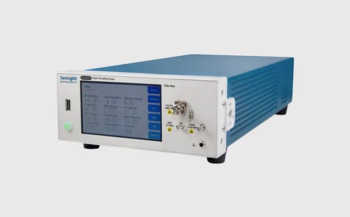
12 GHz Sampling Oscilloscope
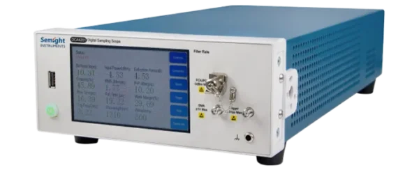
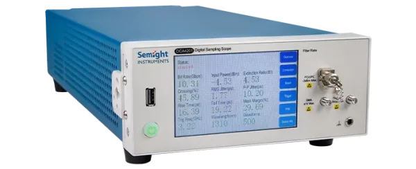
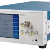
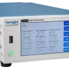
DCA4201 is a sampling oscilloscope, which is designed based on equivalent-time sampling and eye diagram reconstruction technology, it offers a low-cost solution for high-precision measurement of high-speed optoelectronic digital signals.
Features

Fast Sampling
Fast sampling rate 100K

Extinction Ratio Correction
Support extinction ratio correction

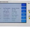
Eye Diagram Test
Automatic eye diagram Margin testing(Mask Margin)

Standard Filter
Covers 1.25 – 12.5 Gbps data rates
Functions and Advantages
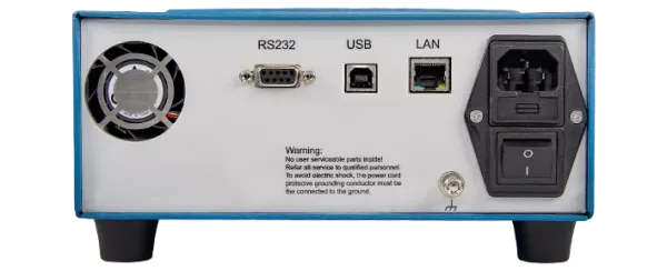
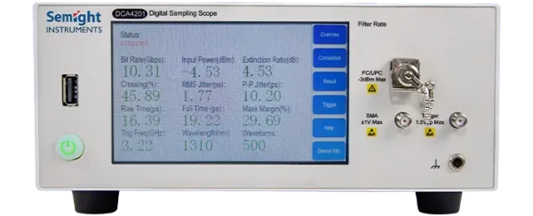
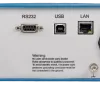
Multi-port Integrated Design
Small size( about ¼ of traditional sampling oscilloscope), greatly reduces required space.
Default configuration is 1 optical + 1 electrical(20G BW), support testing optical signal and electrical signal simultaneously.
Differential electrical port is available by option, and support 10G and below rate electrical eye diagram measurements.
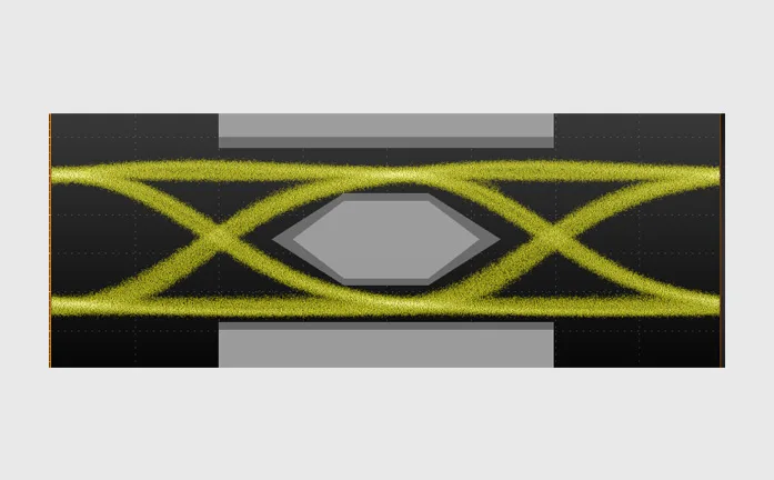
Calibrated Reference Receiver
Meets industry frequency response tolerances
Semight DCA4201 sampling oscilloscope (2.5G)
Calibrated Reference Receiver
Semight DCA4201 sampling oscilloscope(10G)
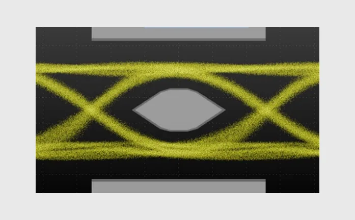
With Extinction Ratio Correction Factor/dark Current Self-calibration and Other Algorithms
Test results are closely match with industry standards.
| Module under test | RMS Jitter (ps) | Crossing (%) | Rise Time 20%~80% (ps) |
Extinction Ratio (dB) | Template Margin Mask Margin (%) |
|
| DUT1 | Semight DCA4201 | 11.69 | 52.04% | 153.86 | 10.44 | 28.91% |
| Absolute Deviation | 0.26 | 0.06% | 2.34 | 0.12 | 1.20% | |
| Relative Deviation | 2.27% | -0.12% | -1.50% | -1.14% | 4.37% | |
| DUT2 | Semight DCA4201 | 7.73 | 50.30% | 149.56 | 11.31 | 40.63% |
| Absolute Deviation | -0.1 | 0.06% | 2.34 | 0.12 | 1.20% | |
| Relative Deviation | -1.28% | -0.20% | -3.76% | -2.25% | 3.65% |
Optical Channel Specifications
| Items | Description |
| Optical Channel Bandwidth[1] | 12 GHz |
| Fiber Optic Input | 62.5/125 μm FC/UPC (Single-mode/multi-mode) |
| Wavelength Range | 750 – 1650 nm |
| Factory Calibration Wavelength | 850/ 1310/ 1550 nm ±10 nm[2] |
| Standard Rate[3]
(filter) |
1.25 Gbps 2.5 Gbps 3.125 Gbps 4.25 Gbps 6.25 Gbps 10.3125 Gbps 12.5 Gbps |
| ADC Resolution | 14 Bit |
| Test Sensitivity[4] | -10 dBm@typ. |
| Measurement Consistency[5] | Average power: ±0.1 dB
Extinction ratio: ±0.3 dB Template margin: ±5 %(After calibration) |
| Maximum input
(No destruction of peak power) |
2 mW (+5 dBm) [6] |
| Maximum input
(Linear test range) |
0.5 mW (-3 dBm) |
| Average power measurement range | -20 dBm to -3 dBm |
| Average power monitoring accuracy[7] | Single mode ±5% ±200 nW ± connector uncertainty
Multi-mode (eigenvalue) ±10% ±200 nW ± connector uncertainty |
| Input return loss
(FC/UPC) |
>20 dB@850 nm
>35 dB@1310 nm |
[1]The optical bandwidth is represented by the optical power drop at the 3 dB point, that is, it describes the -3 dBo bandwidth here (-3 dBo=-6 dBe)
[2]The ±10 nm here is the wavelength error of the light source
[3]Only a few application scenarios are listed; for other application scenarios, please refer to the document’s selection information section or consult sales
[4]This parameter is not used to characterize the performance indicators of the instrument, but is calculated from noise characteristics. Its meaning is the power value when performing a Mask test using an ideal eye diagram, influenced only by the oscilloscope’s inherent noise, and the template margin is close to 0%. In actual testing scenarios, the specific minimum power point that can be tested is also related to the quality of the signal under test.
[5]This parameter is not used to characterize the performance indicators of the instrument. Its meaning is to test with an ideal signal, and the difference between the oscilloscope’s calculated results and the theoretical calculation results. In actual testing scenarios, test consistency is related to the quality of the actual signal
[6]Destructive experiments were conducted by gradually increasing the input optical power (step 0.1 dBm). In practical applications, due to the instability of the light source, do not maintain the input optical signal at +5 dBm or above, as this may lead to a decline in product performance or damage
[7]Due to changes in the mode conditions, the measured power variation in multimode fiber will be greater than that in single-mode fiber. If the user needs to perform the most accurate power measurement, a power meter can be used for multimode power measurement
Electrical Channel Specifications
| Electrical Channel Bandwidth | 20 GHz[1] |
| Rise Time(10%~90%) | 20 ps |
| Max Input Amplitude | <1 V |
| RMS Noise | <2 mV (typ.) |
| Electrical Sensitivity | <24 mV |
| Input impedance | 50Ω |
| Reflection | 10% |
| ADC Resolution | 14 Bit |
| Input Connector | SMA Female |
[1]This describes the electrical port -3 dBe bandwidth. After the test system is unembedded, it is measured using a frequency sweep method (± uncertainty)