
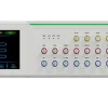
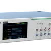
rBT2250
rBT2250
25G Burst Mode Bit Error Ratio Tester
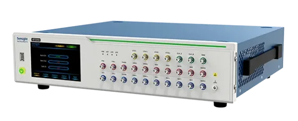
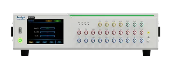
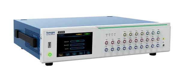
Semight rBT2250 is a Burst Mode Bit Error Ratio Tester to evaluate 10G/25G/50G OLT (Optical Line Terminal) receiver performance in burst mode. rBT2250 provides 2 independent pattern generator/ error detector channels, and provide laser enable/ receiver reset/ RSSI trigger signals and SD signal detect function. With built-in burst clock data recovery, clock would be recovered from the burst data every time. It is a must in long fiber testing. The high integration multi-channel design of rBT2250 make it the best choice for burst bit error ratio analysis.
Features

Multi-rate
Burst Rate:9.953/ 10.3125/12.4416/
24.8832/ 25.78125 GBaud

Downlink Continuous Error Bits Testing Channel
Optional 1 channel with NRZ up to 25Gbps
or 2 channels with NRZ/PAM4 up to 50Gbps

Control Signal Matching
Provides 2 synchronous ONU laser enable control signals
or 2 synchronous reset control signals

Supports LOS/SD Signal Measurement
Each burst channel has the function of detecting LOS/SD signals separately,
which can detect the edge position and level of LOS/SD signals

Rich Trigger Signal
Supports 1 RSSI Trigger signal or 1 Trigger signal
Supports LOS/SD signal measurement

High Efficiency
Quick configuration download and fast hardware response speed
Built-in CDR

Fully Match ATE Application
With powerful and flexible database management capabilities
Features and Benefits
Flexible Burst Timing Configuration
Capable of dual-packet burst timing configuration with synchronous control signal changes.
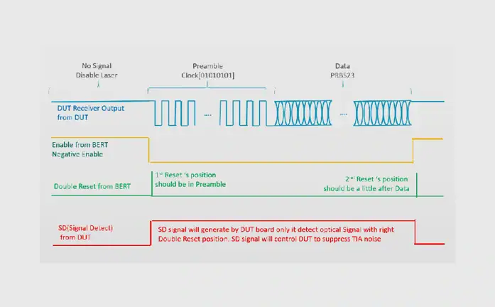
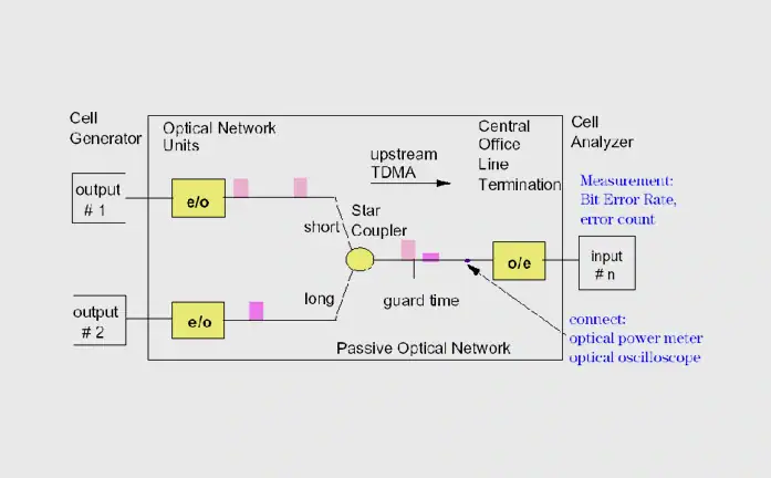
Double Packet Test
Each data packet has different attenuation, there are transitions between the phases of different data packets, and there are long consecutive “1” and “0” in the data packet.
Need to simulate the worst 2 ONU signal generation.
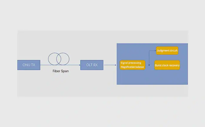
Built-in Clock Recovery, Supports Long Fiber Test
The built-in clock recovery enables the rBT2250 to work in a real long-fiber working environment, which is basically impossible in other solutions commonly used in the industry, because those systems do not support clock recovery and cannot adapt to the effects of long-fiber on delay and jitter.
TX Specification
| Type | Item | Description |
| Pattern Generator Specification | Output | Differential/Single-ended NRZ |
| Terminal | AC Coupling | |
| Output Impedance | 100 Ω ± 10% | |
| Pattern | PRBS7, 15, 23, 31, SSPR, Custom Defined Pattern and CID | |
| Burst Signal Rate (GBaud) [1] | 9.953/10.3125/12.4416/24.8832/25.78125 | |
| Frequency Accuracy | ±50 ppm (typical) | |
| Output Amplitude (differential) | 100-600mVpp (typical) [2] | |
| Rise Time [3]
(20–80%) |
<20ps (typical) | |
| Fall Time [3]
(20–80%) |
<20ps (typical) | |
| Random Jitter [4] | <1ps (typical) | |
| Laser Enable(TXEN) | LVTTL 3.3V | |
| Reset Signal | LVTTL 3.3V, adjustable voltage level, trigger position, and width | |
| Connector | 2.92mm female, 50 Ω | |
| Trigger and Clock Specification | Clock Output Amplitude | >250 mVp-p |
| Output Type | AC Coupled, Single-ended | |
| Div Ratio (Adjustable) | 4/8/16 |
[1]1.25G and 2.5G speeds are not yet compatible
[2]Net measurement value at the transmitter’s end, default pre-emphasis/de-emphasis parameters
[3]Measured with 24.8832 GBaud NRZ signal
[4]Tested with/after Jitter separation
RX Specification
| Type | Item | Description |
| Error Detector Specification | Input | Differential NRZ |
| Terminal | AC Coupled | |
| Input Impedance | 100 Ω ±10% | |
| Input Range (Differential) [1] | 100 ~ 800mVp-p (typical) | |
| RSSI (Differential) [1] | 100mVp-p (typical) | |
| Pattern | PRBS7, 15, 23, 31, CID | |
| Symbol Rate (GBaud) [2] | 9.953/10.3125/12.4416/24.8832/25.78125 | |
| Clock Mode | Built-in Clock Recovery | |
| Connector | 2.92mm female, 50 Ω |
[1]Take care of output amplitude from DUT as the high voltage signal may damage the receiver
[2]1.25G and 2.5G speeds are not yet compatible