
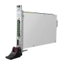
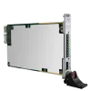
S2013C
S2013C
Single-Channel PXIe SMU
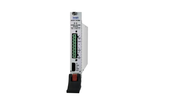
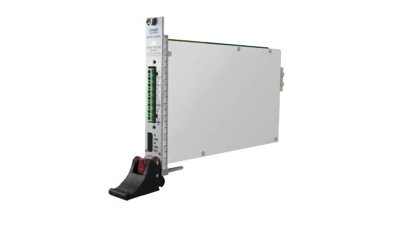
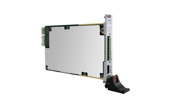
The Semight S2013C is a compact and cost-effective, single-slot, single-channel PXIe Source/Measure Unit (SMU) with the capability to source and measure both voltage and current. It delivers output up to ±200 V, ±1 A (DC), and ±3 A (pulsed) with a constant power of 20 W and supports conventional SMU SCPI commands for easy test code migration. Compatible with existing mainstream PXIe chassis, it offers high integration, enabling easy channel expansion and multi-module synchronization. These features improve efficiency and lower the cost when integrating the SMUs into systems for production test.
Features

High Precision
Resolution up to 100 fA/100 nV

High Range and High-speed Measurement
±200 V, ±1 A (DC), ±3 A (pulsed)
Up to 1M sampling rate can be supported
Adaptive PFC System
Leverages Adaptive PFC
(Precision Fast Control) system
Users can adjust relevant parameters according to load characteristics
Building Multi-channel Parallel Test System
Based on standard PXIe chassis
Easily implement multi-channel parallel testing
Functions and Advantages
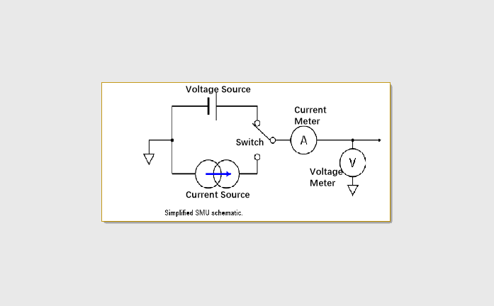
5 Functions In One Card
- Voltage source
- Current source
- Ammeter
- Voltmeter
- Electronic load
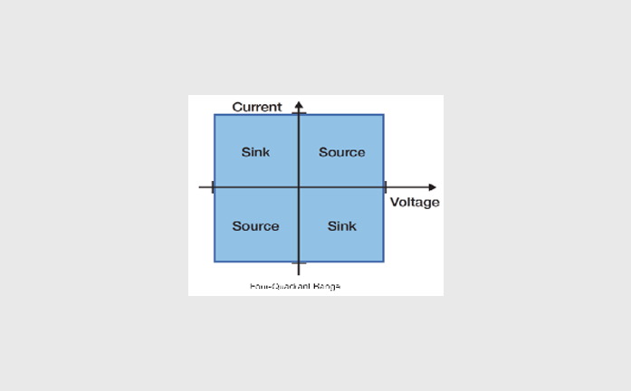
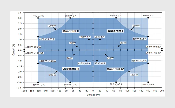
♦ The first and third quadrants are the source: the actual polarity of output V / I follows the source setting.
♦ The second and fourth quadrants are for load: CC and CV cooperate. When the load is used, the polarity of the load setting is opposite to the source polarity.
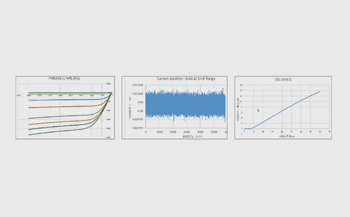
Can Test Various Equipment
Capture More Measurement Data
♦ 6.5-digit resolution: enjoy best-in-class 6.5-digit sourcing and measurement resolution.
♦ 100 fA / 100 nV resolution: excellent sensitivity for setting and measuring.
♦ 1M points / second: provide high-speed measurement, and can quickly set / digitize the rate to any waveform generator / list scan.
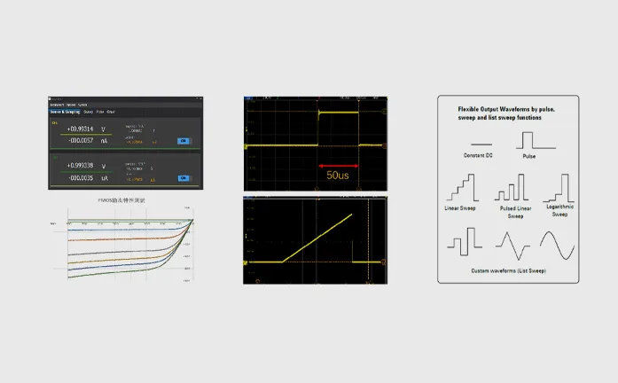
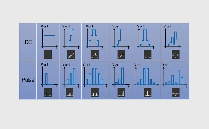
Rich Scanning Function
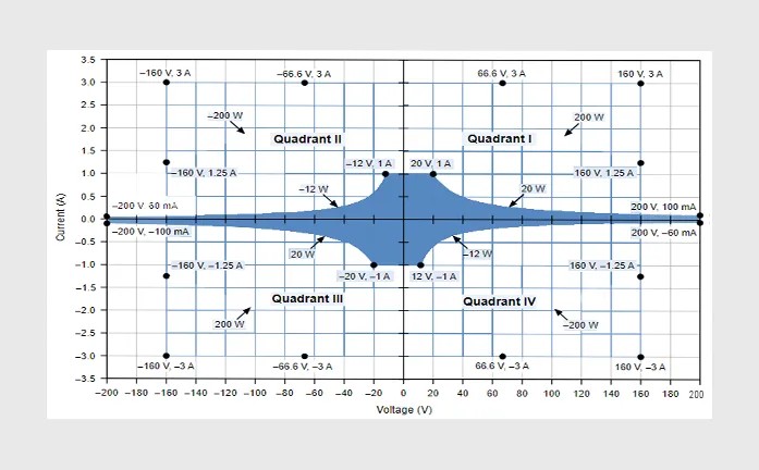
DC I-V Output Capacity
Pulse I-V Output Capacity
Voltage Programming and Measurement Specifications
| Voltage Accuracy | ||||
| Range | Programming Resolution | Accuracy (1 Year) ± (% reading+ offset)[1] |
Typical Noise(RMS) 0.1 Hz-10Hz |
|
| ±200 V[2] | 100 μV | 0.03%+10 mV | 400 μV | |
| ±20 V | 10 μV | 0.03%+1 mV | 50 μV | |
| ±6 V | 1 μV | 0.03%+0.4 mV | 12 μV | |
| ±0.6 V | 100 nV | 0.03%+100 μV | 3 μV | |
| Temperature Coefficient | ±(0.15 × accuracy)/°C (0℃-18℃, 28℃-50℃) | |||
| Overshoot | <±0.1% (typical.normal.step is 10% to 90% range, full range, resistive load) | |||
| Noise 10Hz-20MHz | <5 mVrms, (20V voltage source, 1A resistive load) | |||
[1] Accuracy calculation example: To test the accuracy of a 600mV range with a 120mV output, the tolerance is:
[2] This instrument has a potentially dangerous high voltage (±210 V) output to the HI / Sense HI / Guard terminals. To prevent electric shock, relevant safety precautions must be taken before powering on. Do not connect the Guard terminal to any output, including shorting it to the chassis ground or output LO, as this will damage the instrument
[2] This instrument has a potentially dangerous high voltage (±210 V) output to the HI / Sense HI / Guard terminals. To prevent electric shock, relevant safety precautions must be taken before powering on. Do not connect the Guard terminal to any output, including shorting it to the chassis ground or output LO, as this will damage the instrument
Current Programming and Measurement Specifications
| Current Accuracy
|
||||
| Range | Resolution | Accuracy (1 Year)
± (% reading+ offset) |
Typical Noise (RMS)
0.1 Hz-10 Hz |
|
| ±3 A[3] | 1 μA | 0.03% + 2 mA | 40 μA | |
| ±1 A | 100 nA | 0.03% + 90 μA | 7 μA | |
| ±100 mA | 10 nA | 0.03% + 9 μA | 600 nA | |
| ±10 mA | 1 nA | 0.03% + 900 nA | 60 nA | |
| ±1 mA | 100 pA | 0.03% + 90 nA | 6 nA | |
| ±100 μA | 10 pA | 0.03% + 9 nA | 700 pA | |
| ±10 μA | 1 pA | 0.03% +1 nA | 80 pA | |
| ±1 μA[4] | 100 fA | 0.03% + 200 pA | 20 pA | |
| Temperature Coefficient | ±(0.15 × accuracy)/℃ (0℃-18℃,28℃-50℃) | |||
| Overshoot | <±0.1% (typical. normal mode. step is 10% to 90% range, full range, resistive load) | |||
[3] 3 A range is available only for pulse mode, with typical accuracy
[4] A triaxial cable connection is recommended for low current measurement: Hi to the center conductor, Guard to the inner shield, and the outer shield to protective ground; LO to the center conductor, with the inner shield unconnected, and the outer shield to protective ground. The rated insulation voltage of the triaxial cable must be a minimum of 250 V
Pulse Source Specifications
| Minimum Programmable Pulse Width | 100 μs | |||
| Pulse Width Programming Resolution | 1 μs | |||
| Pulse Width Programming Accuracy | ±10 μs | |||
| Pulse Width Jitter | 2 μs | |||
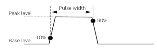
| Pulse Width Definition | The time from 10% leading to 90% trailing edge as follows | |||
| Maximums | Maximum Pulse Width | Maximum Duty Cycle | |
| 0.1 A/200 V | DC, no limit | 100% | |
| 1 A/20 V | DC, no limit | 100% | |
| 3 A/66.6 V | 1 ms | 5% | |
| 3 A/160 V | 400 μs | 2% | |
Typical Pulse Performance
| Source | Maximum Output | Typical Rise Time[5] | Typical Settling Time[6] | Test load |
| Voltage | 160 V | 800 μs | 1.2 ms | No load |
| 5 V | 50 μs | 100 μs | No load | |
| Current | 3A~1 mA | 90 μs | 250 μs | Full load[7] |
| 100μA ~10 μA | 150 μs | 400 μs | Full load[7] | |
| 1 μA | 800 μs | 1.2 ms | Full load[7] |
[5] Time required for the pulse leading edge to rise from 10% to 90%
[6] Time required for the pulse to reach within 1% of final value
[7] Test conditions: Normal mode, resistive full load, voltage rises to 6 V
Sampling Rate and NPLC Setting
| Setting | Range | |||
| NPLC | 0.00005 PLC ~ 10 PLC | |||
| Sampling Rate | 5 sps ~ 1 Msps | |||
Typical Output Settling Time
| Source | Range | Output Settling Time[8] | Condition | ||
| Fast[9] | Normal | Slow | |||
| Voltage | 200 V | <600 μs | <2 ms | <2 ms | Time required to reach within 0.1 % of final value at open load condition. Step is 10% to 90% range |
| 20 V | <80 μs | <150 μs | <800 μs | ||
| 6 V | <60 μs | <100 μs | <300 μs | ||
| 0.6 V | <60 μs | <60 μs | <60 μs | ||
| Current | 3 A~1 mA | <100 μs | <180 μs | <0.8 ms | Time required to reach within 0.1% (0.3% for 3A range) of final value at short condition. Step is 10% to 90% range |
| 100μA~10 μA | <150 μs | <250 μs | <0.8 ms | ||
| 1 μA | <1 ms | <1 ms | <1 ms | ||
[8] Output transition speed:Fast, Normal, Slow. Users can adjust the APFC parameters based on the load characteristics to obtain precision, and fast output characteristics
[9] Slow mode is recommended for overshoot sensitive equipment, Fast mode may have overshoot on output in some condition