
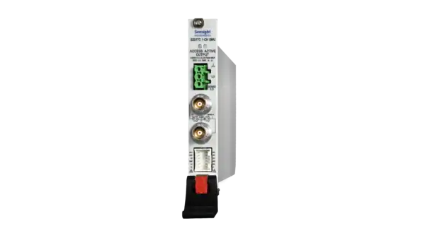
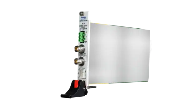
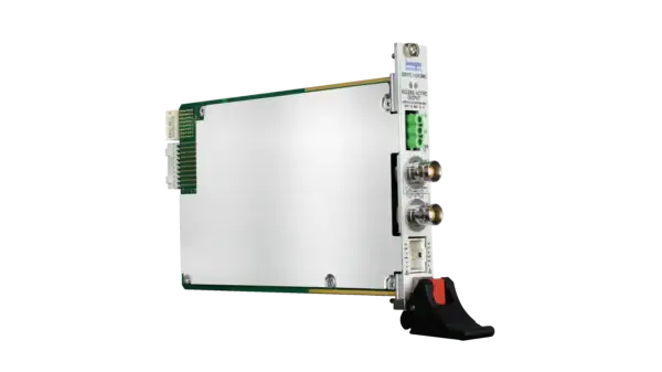
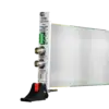
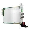
S2017C
S2017C
High Precision SMU
The S2017C by Semight is a compact, cost-effective, single-slot, single-channel Precision Source/Measure Unit (SMU). It can simultaneously output and measure voltage and current, providing up to ±200 V, ±1 A, and 20 W constant power output. Supporting traditional SMU SCPI commands, it makes test code migration quick and easy. It’s compatible with mainstream PXIe chassis and supports multi-card synchronization for integration into production test systems, enhancing test efficiency and reducing costs.
Features

APFC System
Modify APFC parameters
Adjust relevant parameters
To achieve precise and fast output

High Range
Range: ± 200 V, ±1A(DC/pulse)
High Resolution
The minimum measurement resolution can reach 0.1 fA/100 nV
High Sampling Rate
Up to 1MS/s ADC sampling rate

Sweep Mode
Supports single-sided and dual-sided linear, logarithmic, and list sweep modes.
The interval is configurable from 1μs to 16s, with a maximum of 106 points per sweep

Sensing Mode
Supports 2-wire or 4-wire (remote sensing) connections.
The maximum sensing lead resistance is 1 kΩ (for rated accuracy)
The maximum voltage between remote sensing output and sensing terminal is 2 V

Auto Ranging
Supports auto-ranging for both spot and sweep measurement.
For overshoot-sensitive devices, it is recommended to turn off the output before switching ranges
Protection
Features over-temperature protection
Features other over-current and over-voltage protections
If the board indicator remains off, hardware damage may be present.
Functions and Advantages
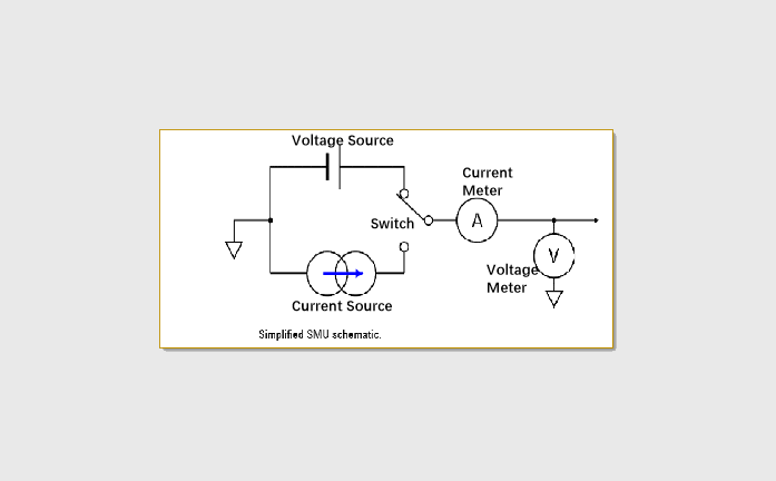
5 Functions In One Card
Voltage source
Current source
Ammeter
Voltmeter
Electronic load
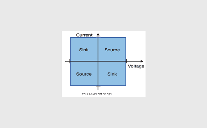
♦ The first and third quadrants are the source: the actual polarity of output V / I follows the source setting.
♦ The second and fourth quadrants are for load: CC and CV cooperate. When the load is used, the polarity of the load setting is opposite to the source polarity.
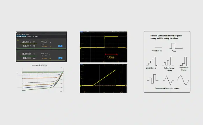
Can Test Various Equipment
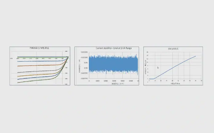
Capture More Measurement Data
♦ 6.5-digit resolution: Enjoy best-in-class 6.5-digit sourcing and measurement resolution.
♦ 0.1 fA / 100 nV resolution: excellent measurement sensitivity.
♦ 1 MS/s sampling rate: provide high-speed measurement, and can quickly set / digitize the rate to any waveform generator (list scan).
Rich Scanning Function
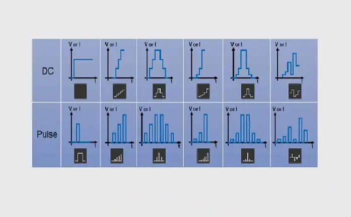
Voltage Programming and Measurement specifications
| Voltage Accuracy | ||||
| Range | Resolution | Accuracy (1 Year)
±(% reading + offset)[1] |
Typical Noise (RMS)
0.1 Hz – 10 Hz |
|
| ±200 V[2] | 100 μV | 0.03% + 10 mV | 0.4 mV | |
| ±40 V | 10 μV | 0.03% + 2 mV | 100 μV | |
| ±20 V | 10 μV | 0.03% + 1 mV | 50 μV | |
| ±2 V | 1 μV | 0.03% + 100 μV | 10 μV | |
| ±0.6 V | 100 nV | 0.03% + 50 μV | 2 μV | |
| Temperature Coefficient | ±(0.15 × Accuracy)/℃(0℃ – 18℃, 28℃ – 50℃) | |||
| Overshoot | <±0.1% (Typical, Normal, step is 10% to 90% of range, full range, resistive load) | |||
| Noise
10 Hz – 20 MHz |
< 5 mVrms, 20 V voltage source, 1 A resistive load | |||
[1] Accuracy calculation example: To test the accuracy of a 600 mV range with a 120 mV output, the tolerance is:

[2] This instrument has a potentially dangerous high voltage (±210 V) output to the HI / Sense HI / Guard terminals. To prevent electric shock, relevant safety precautions must be taken before powering on. Do not connect the Guard terminal to any output, including shorting it to the chassis ground or output LO, as this will damage the instrument.
Current Programming and Measurement Specifications
| Current Accuracy | ||||
| Range | Resolution | Accuracy (1 Year)
±(% reading + offset) |
Typical Noise (RMS)
0.1 Hz – 10 Hz |
|
| ±1 A | 100 nA | 0.03% + 90 μA | 4 μA | |
| ±100 mA | 10 nA | 0.03% + 9 μA | 600 nA | |
| ±10 mA | 1 nA | 0.03% + 900 nA | 60 nA | |
| ±1 mA | 100 pA | 0.03% + 90 nA | 6 nA | |
| ±100 μA | 10 pA | 0.03% + 9 nA | 700 pA | |
| ±1 μA[3] | 100 fA | 0.03% + 200 pA | 20 pA | |
| ±10 nA[3][4] | 10 fA | 0.06% + 9 pA | 600 fA | |
| ±1 nA[3][4] | 1 fA | 0.1% + 3 pA | 60 fA | |
| ±100 pA[3][4] | 1 fA | 0.3% + 500 fA | 80 fA | |
| ±10 pA[3][4][5] | 1 fA | 0.46% + 100 fA | 10 fA | |
| ±1 pA[3][4][5] | 0.1 fA | 0.9% + 50 fA | 3 fA | |
| Temperature Coefficient | ±(0.15 × accuracy)/℃ (0℃ – 18℃, 28℃ – 50℃) | |||
| Overshoot | <±0.1% (Typical. Normal mode. Step is 10 % to 90 % range, full scale range , resistive load) | |||
[3] For low-level current measurements, it is recommended to use a triaxial cable connection. If a triaxial terminal is converted to a standard wiring output, the current accuracy of the instrument will be compromised.
[4] Test Conditions: NPLC set to 10 PLC.
[5] The 10 pA and 1 pA ranges are accessible only when the PSU is connected.
Resistance Measurement Specifications
| Resistance Accuracy | ||||
| Range | Resolution | Default
Test Current |
Accuracy (1 Year)
±(% reading + offset) |
|
| 600 mΩ | 100 nΩ | 1 A | 0.07 % + 50 μΩ | |
| 6 Ω | 1 μΩ | 100 mA | 0.07% + 500 μΩ | |
| 60 Ω | 10 μΩ | 10 mA | 0.07% + 5 mΩ | |
| 600 Ω | 100 μΩ | 1 mA | 0.07% + 50 mΩ | |
| 6 KΩ | 1 mΩ | 100 μA | 0.07% + 500 mΩ | |
| 60 KΩ | 10 mΩ | 10 μA | 0.15% + 5 Ω | |
| 600 KΩ | 100 mΩ | 1 μA | 0.08% + 50 Ω | |
| 6 MΩ | 1 Ω | 100 nA | 0.26% + 500 KΩ | |
| 60 MΩ | 10 Ω | 10 nA | 0.18% + 5 KΩ | |
| 600 MΩ | 100 Ω | 1 nA | 0.43% + 50 KΩ | |
| 6 GΩ | 1 KΩ | 100 pA | 1.35% + 500 KΩ | |
| Temperature Coefficient | ±(0.15 × Accuracy)/℃(0℃ – 18℃, 28℃ – 50℃) | |||
| Manual Current Source Resistance Measurement (4-Wire) | Total Error = Measured Voltage / Current Source Set Current = Resistance Reading x (Voltage Source Range Gain Error Percentage + Ammeter Range Gain Error Percentage + Current Source Range Offset Error / Set Current) + (Voltage Source Range Offset Error / Set Current Value)
Example: Current Source Set Current = 1 A, Voltage Measurement Range = 600 mV Total Error = (0.03% + 0.03% + 90 μA/1 A) + (50 μV/1 A) ≈ 0.07% + 50 μΩ |
|||