
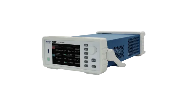
S2035H
S2035H
Single-channel High-precision SMU
The S2035H is a high-precision, compact, cost-effective, single channel benchtop Source/Measure Unit (SMU) with a wide range of voltage source (± 200V) and current source (± 1A DC and ± 3A pulse) capabilities. It provides the excellent accuracy with 6 ½ digits display resolution (minimum 1fA/100nV) and nice graphical user interface (GUI) on superior color LCD.
Features

High Range
Range: ±200 V, ±1 A(DC), ±3A (pulse)

High Resolution
The minimum measurement resolution can reach 1 fA/100 nV
High Sampling Rate
Supports up to 1M ADC sampling rate
Threshold Trigger
Hardware high-speed IO, capable of threshold triggering, enabling efficient interaction between output measurement values and user systems
DC I-V Out Capability
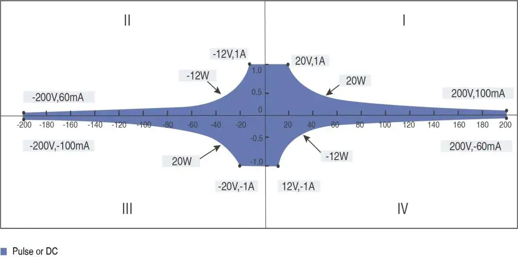
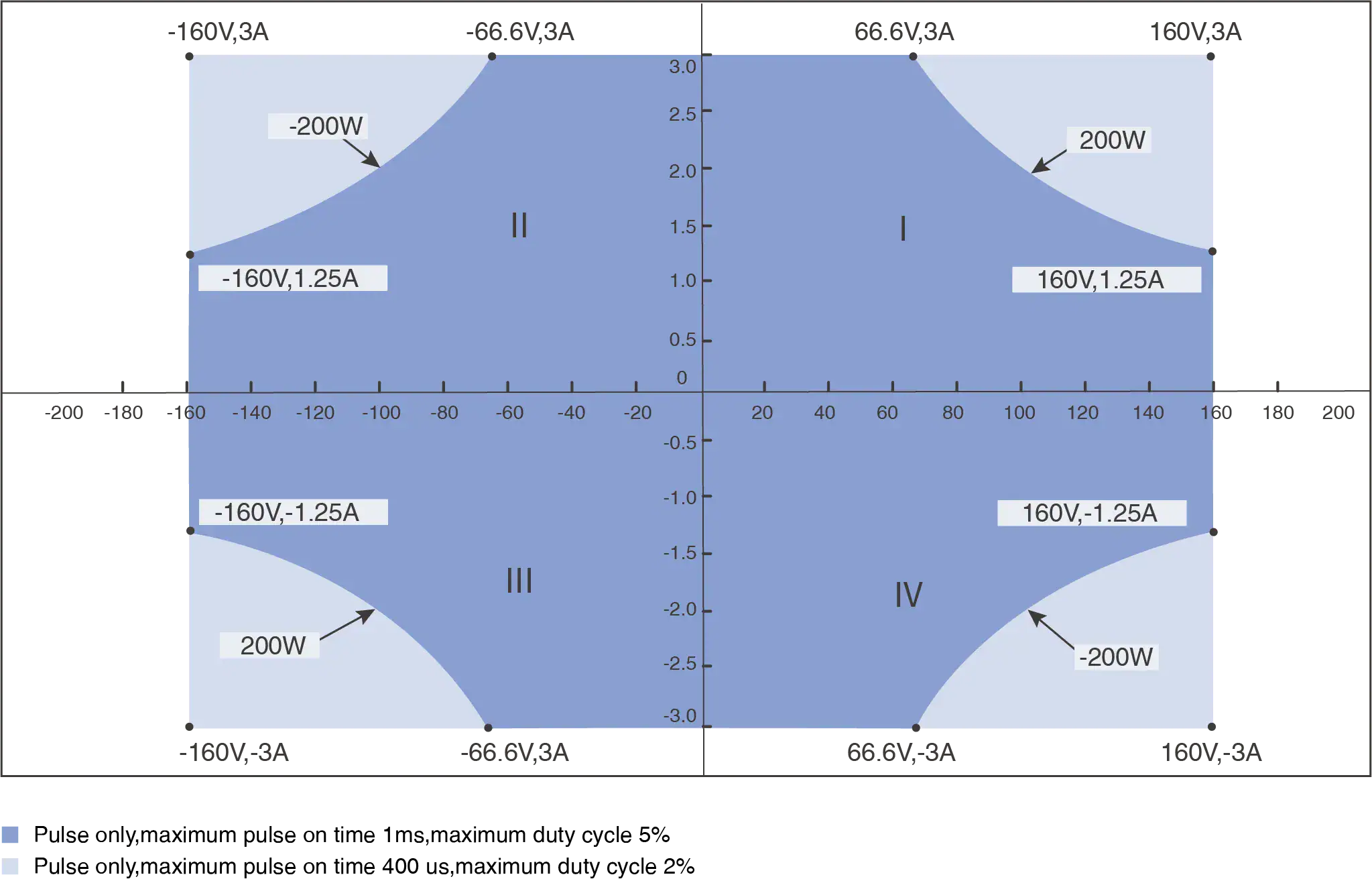
Pulse Output Capability
Voltage Source/ Measurement Specifications
| Voltage Programming Accuracy | ||||
| Range | Programming Resolution | Accuracy (1 Year)
± (% reading+ offset) |
Typical Noise (RMS)
0.1 Hz-10 Hz |
|
| ±200 V | 100 μV | 0.03%+10 mV | 0.4 mV | |
| ±40 V | 10 μV | 0.03%+2 mV | 100 μV | |
| ±20 V | 10 μV | 0.03%+1 mV | 50 μV | |
| ±2 V | 1 μV | 0.03%+100 μV | 10 μV | |
| ±0.6 V | 100 nV | 0.03%+50 μV | 2 μV | |
| Temperature Coefficient | ±(0.15 × accuracy)/℃ (0℃-18℃,28℃-50℃) | |||
| Settling Time | <50 μs (typical) | |||
| Overshoot | <±0.1% (typical. normal mode. step is 10 % to 90 % range, full range, resistive load) | |||
| Noise 10Hz-20MHz | 20V voltage source,1A resistive load, <5 mVrms | |||
Current Source/ Measurement Specifications
| Current Programming Accuracy | ||||
| Range | Programming Resolution | Accuracy (1 Year)
± (% reading+ offset) |
Typical Noise (RMS)
0.1 Hz-10 Hz |
|
| ±3 A[1] | 1 μA | 0.03% + 2 mA | 20 μA | |
| ±1 A | 100 nA | 0.03% + 90 μA | 4 μA | |
| ±100 mA | 10 nA | 0.03% + 9 μA | 600 nA | |
| ±10 mA | 1 nA | 0.03% + 900 nA | 60 nA | |
| ±1 mA | 100 pA | 0.03% + 90 nA | 6 nA | |
| ±100 μA | 10 pA | 0.03% + 9 nA | 700 pA | |
| ±1 μA | 100 fA | 0.03% + 200 pA | 20 pA | |
| ±10 nA[2] | 10 fA | 0.06% +9 pA | 600 fA | |
| ±1 nA[2] | 1 fA | 0.1% +3 pA | 60 fA | |
| ±100 pA[2] | 1 fA | 0.3% +1 pA | 30 fA | |
| Temperature Coefficient | ±(0.15 × accuracy)/℃ (0℃-18℃, 28℃-50℃) | |||
| Settling Time | <100 μs (typical) | |||
| Overshoot | <±0.1% (typical. normal mode. step is 10% to 90% range, full range, resistive load) | |||
[1] 3 A range is available only for pulse mode, accuracy specifications for 3 A range are typical
[2] Additional specification conditions: 10 PLC setting
Pulse Source Specifications (4W)
| Minimum Programmable Pulse Width | 100 μs |
| Pulse Width Programming Resolution | 1 μs |
| Pulse Width Programming Accuracy | ±10 μs |
| Pulse Width Jitter | 2 μs |
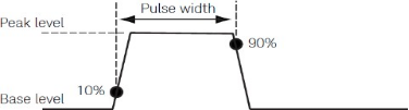
| Pulse Width Definition | The time from 10% leading to 90% trailing edge as follows |
| Item | Maximums | Maximum Pulse Width | Maximum Duty Cycle |
| 1 | 0.1 A/200 V | DC, no limit | 100% |
| 2 | 1 A/20 V | DC, no limit | 100% |
| 3 | 3 A/66.6 V | 1 ms | 5% |
| 4 | 3 A/160 V | 400 μs | 2% |
Typical Pulse Performance(4W)
| Source | Maximum Output | Typical Rise Time [1] | Typical Settling Time[2] | Test Load |
| Voltage
|
160 V | 800 μs | 1.2 ms | NO load |
| 5 V | 40 μs | 100 μs | NO load | |
| Current
|
3 A~1 mA | 90 μs | 250 μs | Full load[3] |
| 100 μA | 120 μs | 400 μs | Full load[3] | |
| 1 μA | 300 μs | 600 μs | Full load[3] | |
| 10 nA | 5 ms | 10 ms | Full load[3] | |
| 1 nA | 10 ms | 50 ms | Full load[3] | |
| 100 pA | 100 ms | 500 ms | Full load[3] |
[1] Leading edge, the time from 10% leading to 90% leading
[2] The time required from pulse out 0 to reach within 1% of final value
[3] Test condition: Normal, resistive load 6V maximum output
Typical Output Settling Time
| Source | Range | Output Settling Time[1] | Condition | ||
| Fast[2] | Normal | Slow | |||
| Voltage | 200 V | <500 μs | <1 ms | <2 ms | Time required to reach within 0.1% of final value at open load condition. Step is 10% to 90% range |
| 40 V | <200 μs | <400 μs | <900 μs | ||
| 20 V | <60 μs | <100 μs | <500 μs | ||
| 2 V | <50 μs | <50 μs | <50 μs | ||
| 0.6 V | <50 μs | <50 μs | <50 μs | ||
| Current | 3 A~1 mA | <50 μs | <100 μs | <0.8 ms | Time required to reach within 0.1% (0.3% for 3 A range) of final value at short condition. Step is 10% to 90% range |
| 100 μA | <100 μs | <150 μs | <0.8 ms | ||
| 1 μA | <1 ms | <1 ms | <1 ms | ||
| 10 nA | <10 ms | <10 ms | <10 ms | ||
| 1 nA | <50 ms | <50 ms | <50 ms | ||
| 100 pA | <500 ms | <500 ms | <500 ms | ||
[1] Output transition speed: Fast, Normal, Slow. Users can adjust the APFC parameters based on the load characteristics to obtain precision, and fast output characteristics
[2] Slow mode is recommended for overshoot sensitive equipment. Fast mode may have overshoot on output in some condition
Sampling Rate and NPLC Setting
| Setting | Range |
| NPLC | 0.00005 PLC ~ 10 PLC |
| Sampling Rate | 5 sps ~ 1 Msps |
Derating Accuracy with PLC Setting(PLC<1)
Add % of range using the following table for measurement with PLC < 1
| PLC | Range | |||||||
| 0.6 V | 2 V | 6 V | 20 V | 200 V | 100 pA to
1 μA |
100 μA to
100 mA |
1 A to 3 A | |
| 0.1 | 0.02% | 0.02% | 0.01% | 0.01% | 0.01% | 0.02% | 0.01% | 0.01% |
| 0.01 | 0.3% | 0.3% | 0.3% | 0.03% | 0.02% | 0.2% | 0.02% | 0.02% |
| 0.001 | 3.20% | 3.20% | 3.20% | 0.04% | 0.10% | 2.50% | 0.03% | 0.03% |