
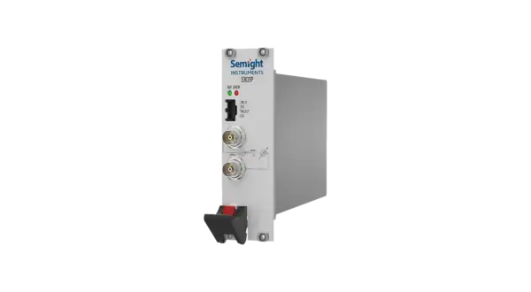
S3029P
S3029P
Precision PSMU
S3029P by Semight is a standard single-channel pulse current source/ measurement unit. It can output ±2 A high-precision current pulses. S3029P covers the broad applications: semiconductor device testing, laser driver, material research, EMC inspection, etc. It enables one-stop solution to meet the challenges in current pulse measurement in many applications.
Features

Pulse Width
Minimum 3 μs, maximum 500 μs
Suitable for faster tested devices to better avoid the impact of temperature on test results

High-speed Measurement
ADC up to 125 MSa/s

High Range
Range: ±2 A, 10 V
Stronger Load Adaptability
Test loads with different characteristics to ensure that the waveform does not experience overshoot or other distortions

High Speed Synchronization
Single-channel and multi-mode collaborative measurement

Real Time Reading of DUT Voltage Drop for Pulse Current
No additional equipment required, precise monitoring of current testing conditions, real-time reading back of test results
Functions and Advantages
- Working conditions
- Temperature 23 ℃± 5 ℃
- Relative humidity<70%
Pulse Current Output
| Parameter |
Specification | ||||||
| Current Accuracy | Range | Programming Resolution | Accuracy[1](1Y) ±(%RD+Offset) |
Typical Noise[3](RMS) 1Hz-10MHz |
|||
| ±150mA[2] | 20μA | 0.1%+0.2mA | 0.2mA | ||||
| ±750mA | 20μA | 0.1%+0.3mA | 0.3mA | ||||
| ±2A | 40μA | 0.1%+2mA | 0.4mA | ||||
| Maximum Load Voltage Drop | 10V | ||||||
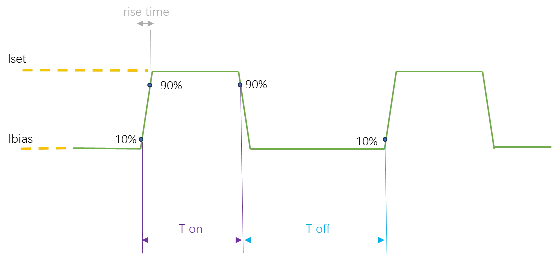
| Pulse Width Resolution | 80ns | ||||||
| Maximum Pulse Width T on-max | 500μs | ||||||
| Minimum Pulse Width T on-min | 3μs | ||||||
| Pulse Minimal Cut-off Time Toff-min | 100μs | ||||||
| Pulse Width Accuracy | 100ns[4] | ||||||
| Pulse Width Jitter | 500ns(typ.) | ||||||
| Rising Time(10%-90%) | <400ns[4][5][6] | ||||||
| Pulse Overshoot | <3%[4][5][6] | ||||||
| Current Regulation Rate |
Line Regulation | 0.05% of Range |
|||||
| Load Regulation | ±100μA |
||||||
| Duty Cycle Limit[7] | D≤50%, where: D < 3/[(Vsp – Vload)x(|Iset|- |Ibias|)] |
||||||
| Maximum Number of Pulses per Scan | 65535 | ||||||
[1] Test Setup:current pulse width 500us, use of high accuracy ammeter,measurement speed 0.02 NPLC;
[2] Switched internally, user setting not required;
[3] Use of 10Ω resistance load, measure noise of two terminals,calculated by I=V/R;
[4] Bias current>1mA, pulse width measured from 10 of rising edge 10% to 90% of failing edge 90%;
[5] Load: 0.5Ω resistor;
[6] Total inductance of output lineand DUT<200nH(100k);
[7] Iset:setting current;Ibias:bias current; D:duty cycle;Vsp:programmed source voltage from 5-40V;Vload:voltage drop of load;
Note:In current output mode, the instrument will automatically detect the circuit loop state. In case of external circuit open, it will shut down the output and report error.
Pulse Measurement (both Voltage and Current)
| Parameter | Specification | ||
| Pulse
Voltage Measurement |
Range | Display Resolution | Accuracy ±(%RD+Offset) |
| 6V | 1mV | 0.1%+22mV | |
| 10V | 10mV | 0.1%+24mV | |
| Pulse
Current Measurement |
Range | Display Resolution | Accuracy ±(%RD+Offset) |
| 150mA | 100μA | 0.1%+1mA | |
| 750mA | 100μA | 0.1%+3mA | |
| 2A | 1000μA | 0.1%+15mA | |
| Sense Constrain(PULSE VM) |
Max Votlage between HI and SENSE HI =±10V; |
||
Bias Current
| Parameter | Specification | ||||
| Current Accuracy | Range | Max Current | Programming Resolution | Accuracy ±(%RD+Offset) |
Typical Noise[3](RMS)1Hz-10MHz |
| ±0.15A | 50mA | 20μA | 0.1%+0.2mA | 0.2mA | |
| ±0.75A | 20μA | ||||
| ±2A | 40μA | ||||
Trig Signal
|
Trig Source |
Trig Function | Level | Delay[8](Typical[9]) | Trig Mode |
| PXI0-PXI7 | Trig_IN[10] | / | 500ns | Rising/Falling/Dual Edge |
| PXI0-PXI7 | Trig_OUT[11] | / | 300ns | Rising Edge |
| DIO[12] | Trig_IN | 5V | 500ns | Rising/Falling/Dual Edge |
| DIO | Trig_OUT | 5V | 300ns | Rising Edge |
[8]The delay between trig signal and current pulse;
[9]Test setup:output current>100mA,bias current>1mA;
[10]Trig_In(slave);
[11]Trig_Out(master);
[12]Max input voltage 5V,min input voltage 0V,VOL 1.5V,VOH 3.5V,max output/input current 2mA.