

DCA6201
30/50GHz Sampling Oscilloscope DCA6201
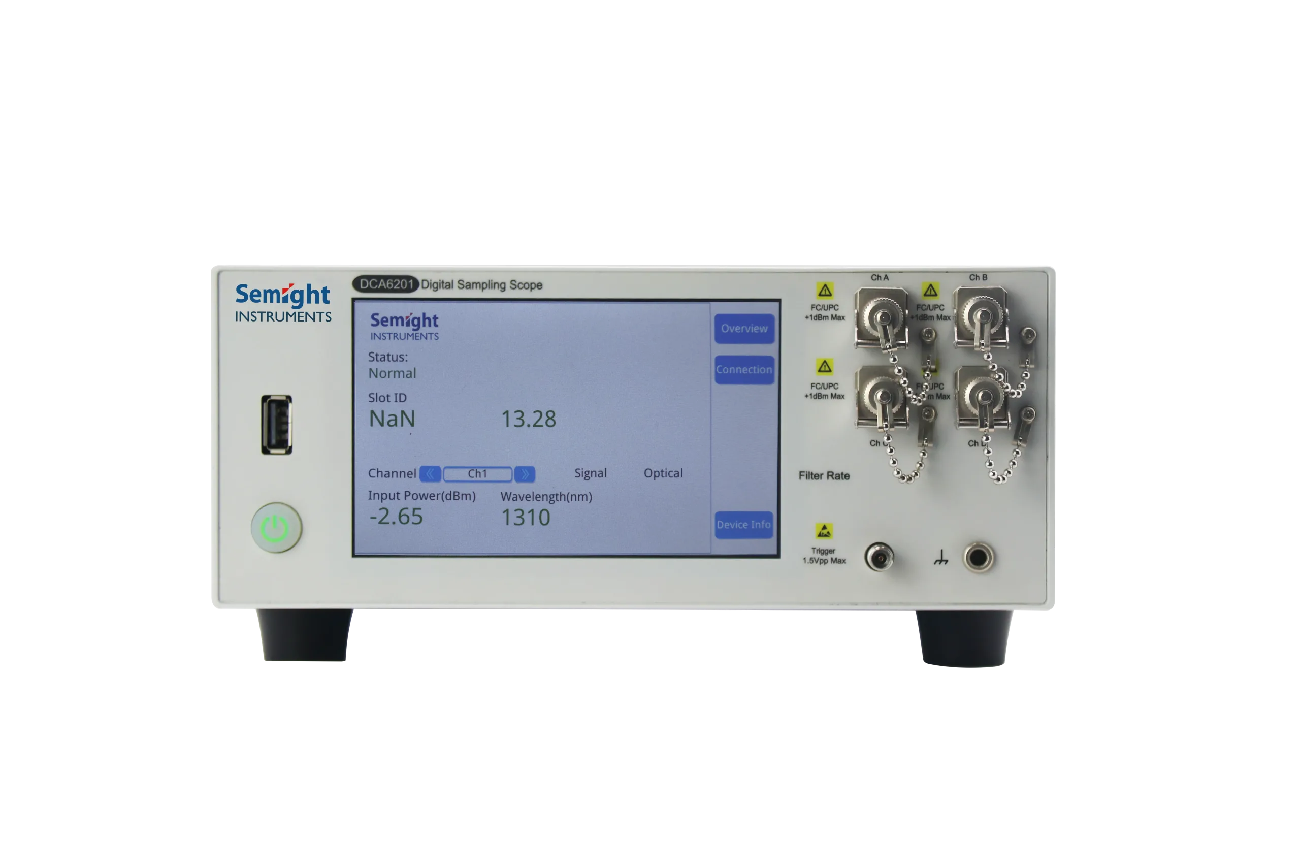
Designed for high-volume manufacturing test applications, the DCA6201 has excellent measurement accuracy comparable to industry-standard DCA oscilloscopes. The DCA6201 is designed for R&D and massive production test applications and supports NRZ/PAM4 signals testing. Optical channels include optical reference receivers for the common 20 to 53GBaud rates, and can simultaneously support up to 4 channels of eye diagram testing.
- Efficient measurement – Support simultaneous measurement of all channels and parallel measurement
- Multiple measurement functions – Meet the normal NRZ and PAM4 eye diagram test parameters
- Automatic test – The remote command control mode is convenient and fast
- Ensure accurate performance – High performance ensures test consistency rates
Features and Benefits
Integrated multi-port design
Small size(about 1/4 of the traditional sampling oscilloscope), saves space;
4 optical ports optional, which can test 4 optical eye diagrams at the same time;
4 differential electrical ports optional, 30G BW, support AOC and other module electrical port parameter tests;


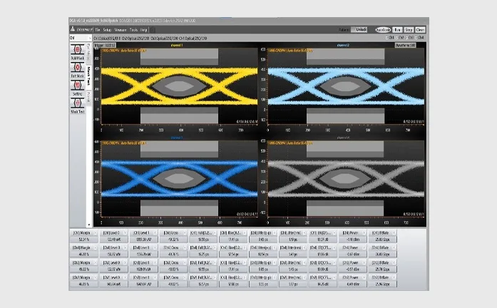
Calibrated reference receiver
Comply with the industry frequency response tolerance, compared with the traditional industry standard sampling oscilloscope, the eye diagram shape consistency is very high;
As shown in the figure, the NRZ eye diagram
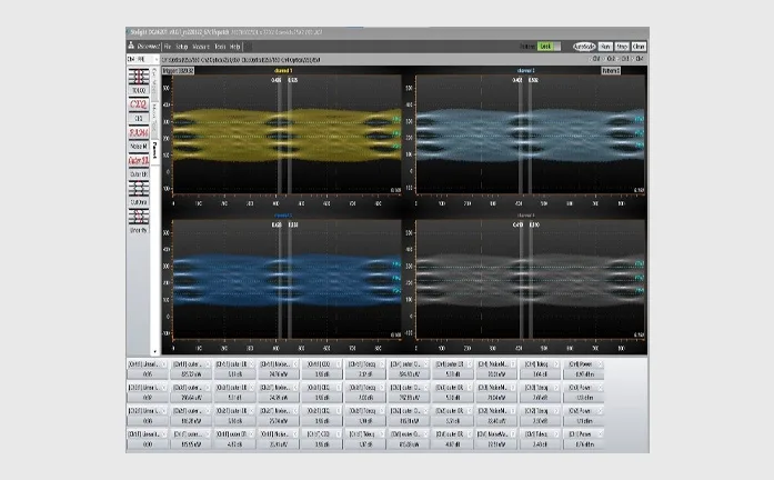
Calibrated reference receiver
Comply with the industry frequency response tolerance, compared with the traditional industry standard sampling oscilloscope, the eye diagram shape consistency is very high;
As shown in the figure is the PAM4 eye diagram

Optical Channel Specifications
| Items | Specifications | |
| DCA6201-B30 | DCA6201-B50 | |
| Optical channel bandwidth[1] | 30 GHz | 50 GHz(IRC Option) |
| Fiber input | 50/125μm FC/UPC (single-mode/multi-mode) | |
| Wavelength range | 800 ~ 1650 nm | |
| Factory Calibrated Wavelengths [2] | 850/1310/1550 nm ±10 nm | |
| Support various data rate according to multi standards (Filters)
|
25.78Gbps (25/50/100 Gb Ethernet)
26.56 Gbps (400 Gb Ethernet) 27.95 Gbps (OTU4) 28.05 Gbps (32×Fiber Channel) 26.5625 GBaud PAM4 28.9 GBaud PAM4 |
53.125 GBaud PAM4
53.125 GBaud NRZ 49.7664 GBaud NRZ (50G PON) 24.8832 GBaud NRZ (50G PON) 12.4416 GBaud NRZ (50G PON) |
| ADC resolution | 14 Bit | |
| Measurement consistency [3] | Average Power:±0.1 dB
Extinction Ratio:±0.3 dB Mask Margin:±5% TDECQ(PAM4):±0.5 dB |
|
| Max Input[4]
(Non-Destruction, Peak) |
5 mW (+7 dBm) | |
| Sensitivity and Linear range [5][6] | NRZ: 0 ~ -8 dBm
PAM4:-1 ~ -7 dBm |
|
| Monitor Average Power Range | -20 dBm ~ +1 dBm | |
| Average power monitor accuracy[7] | Single-mode ±5% ±200 nW ±connector uncertainty
Multimode (characteristic) ± 10% ± 200 nW ± connector uncertainty |
|
| Input return loss
(FC/UPC) |
>23 dB@850nm
>30 dB@1310nm |
|
[1] Optical channel bandwidth define by optical power reduced by 3dB which is -3dBo bandwidth(-3dBo=-6dBe)。
[2] Here the ±10 nm is the source optical wave length error
[3] This parameter is not used to describe instrument specification. It means the difference between test with ideal signal and the theoretical value. In real test scenario, the test consistency related to signal quality.
[4] This value is from damage test by increasing the input optical power step by step (0.1dBm step). In real applications, due to the instability of the optical source, please be aware that not to keep the input optical signal power at+7dBm or above, IT MAY CAUSE THE INSTRUMENTS PERFORMANCE REDUCTION OR EVEN DAMAGE.
[5] Sensitivity is not a part of instrument specifications. It is calculated from characteristic value of noise. It means the power value when influenced only by oscilloscope‘s noise floor, test with ideal eye diagram mask and the mask margin to be close to 0%. The minimal power value is also related to the quality of signal under test in real scenario.
[6] It has difference with different signal(NRZ/PAM4,single-mode/multi-mode).
[7] Due to variations in mode-filling conditions, the measured power in multimode fiber will vary more than the measured power in single-mode fiber. For users needing the most accurate power measurements, use an optical power meter for multimode power measurements.
Electrical Specifications
| Items | Specifications |
| Electrical channel
bandwidth [1] |
33 GHz |
| Input signal type | AC-coupled |
| Input connector | 1.85 mm female(Differential) |
| Dynamic range of input | 500 mVpp |
| DC accuracy | 3 mV@typ. |
| RMS Noise | 1.5 mV@typ. |
| ADC resolution | 14 Bit |
| Max Input Amplitude | ±1 V |
| Impedance | 50±10% Ω |
[1]It’s the electrical channel -3dBe bandwidth. It is measured by frequency sweeping after removal of test system.(±uncertainty)
