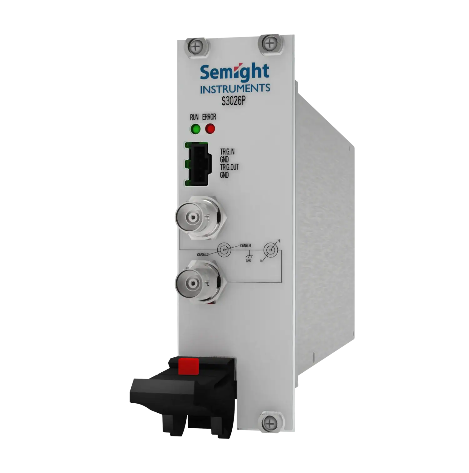
S3026P
S3026P – Semight Instruments Single-Channel PXIe Pulse Current SMU
Semight S3026P is a standard Single-Channel Pulse Current SMU launched for the LiDAR market, supporting high-precision pulse current output and synchronous measurement of pulse current and DUT voltage drop.
S3026P – Semight Instruments Single-Channel PXIe Pulse Current SMU
- Pulse width: minimum 3us, maximum 500us – Suitable for faster tested devices to better avoid the impact of temperature on test results
- High-speed measurement – ADC up to 100MSa/s
- Large range – ±1.5A;10V
- Stronger load adaptability – Test loads with different characteristics to ensure that the waveform does not experience overshoot or other distortions
- High speed synchronization – Multi-channel and multi model collaborative measurement
- Real time reading of DUT voltage drop for pulse current – No additional equipment required, precise monitoring of current testing conditions, real-time reading back of test results
Features and Advantages
Working conditions:
Temperature 23 ℃± 5 ℃
Relative humidity<70%
Pulse Current Source Specification (cannot be used with DC voltage source)
| Current accuracy | Range | Programming Resolution | Accuracy | Accuracy |
| ± (%RD+mA) | ± (%RD+mA) | |||
| (10us pulse width) | (1us pulse width) | |||
| ±150mA | 20uA | 0.1%+0.5mA | 1%+2mA | |
| ±750mA | 40uA | 0.1%+1mA | 1%+10mA | |
| ±1.5A | 100uA | 0.1%+2mA | 1%+20mA | |
| Current noise | Range | Typical Noise (resistive load, RMS) | Typical Noise (resistive load, RMS) | Typical Noise (resistive load, RMS) |
| 10k-20MHz | 10k-10MHz | 10k-1MHz | ||
| ±150mA | 1mA | 0.8mA | 0.5mA | |
| ±750mA | 3mA | 2.5mA | 1.4mA | |
| ±1.5A | 5mA | 4mA | 2.4mA | |
| Maximum load voltage | 10V | 1. Output electrical short; 2. Total cable and DUT inductance < 200nH (100k); 3. Pulse width measurement from rising edge 10% to falling edge 90% |
||
| Pulse width | 80ns | |||
| Programming | ||||
| Resolution | ||||
| Maximum pulse width Ton-max | 500us | |||
| Minimum pulse width Ton-min | 3us | |||
| Pulse minimum turn-off time Toff-min | 500us | |||
| Pulse width accuracy | 100ns | |||
| Pulse width jitter | 80ns (typical value) | |||
| Pulse-period jitter | 500ns (typical value) | |||
| Rise time (10%-90%) | <200ns | |||
| Pulse overshoot | <0.5% | |||
| Current regulation | linear | 0.05% of the range | ||
| load | ±100uA | |||
| Duty cycle | D<3-|Ibias|/[(Vsp-Vload)*(|Iset|-|Ibias|)] | |||
| Iset: programing current; | ||||
| D: duty cycle; | ||||
| Vsp: source protection voltage; | ||||
| Vload: load voltage | ||||
| Maximum number of pulses per scan | 64k | |||
Pulse Source Measurement Specifications
| PULSE | Range | Display resolution | Accuracy± (%RD+mV) | Accuracy± (%RD+mV) | Sample rate | Test condition |
| voltage | (10us pulse width) | (1us pulse width) | ||||
| measure | ||||||
| 6V | 0.1mV | 0.1%+6mV | 0.2%+20mV | 10MSa/s | 1. The sampling rate is the maximum that can be used by the user; | |
| 2. The pulse width condition of the accuracy index refers to the time required from the start of measurement to stability to the accuracy requirements | ||||||
| 10V | 0.1%+10mV | 0.2%+30mV | ||||
| PULSE | Range | Display resolution | Accuracy± (%RD+mA) | Accuracy± (%RD+mA) | Sample rate | |
| Electric current | (under 10us pulse width) | (under 1us pulse width) | ||||
| measure | ||||||
| 150mA | 20uA | 0.1%+0.5mA | 0.2%+1mA | 10Msa/s | ||
| 750mA | 40uA | 0.1%+1mA | 0.2%+2.4mA | |||
| 1.5A | 100uA | 0.1%+2mA | 0.2%+5mA | |||
| Remote Voltage Sense | The maximum voltage between HI and SENSE HI =±10v; | |||||
| (PULSE voltage measurement) | The maximum voltage between LO and SENSE LO =±10v; | |||||
DC Voltage Source Specification (cannot be used with pulse current source)
| Voltage Source (DC) | Range | Programing resolution | Accuracy± (%RD+mV) | Ripple (Vp-p) 10k-20MHz |
Maximum current output |
| ±10V | 1mV | 0.1%+10mV | <10mV | 10mA | |
| Current Measurement (DC) | Range | Display resolution | Accuracy± (%RD+nA) | Sample rate | Normal sampling rate |
| 100uA | 10nA | 0.1%+100nA | 10Msa/s | 10NPLC | |
| 100nA | 10pA | 0.1%+0.1nA | |||
| Voltage Measurement (DC) | Range | Display resolution | Precision | Sample rate | |
| ± (%RD+mV) | |||||
| ±10V | 1mV | 0.1%+10mV | 10Msa/s | ||
| Remote Voltage Sense (When measuring DC voltage) |
The maximum voltage between HI and SENSE HI =±1v; The maximum voltage between LO and SENSE LO =±1v; |
||||
Bias Current Source Specifications
| Current accuracy | Range | Programing resolution | Accuracy | Accuracy |
| ± (%RD+mA) | ± (%RD+mA) | |||
| (10us pulse width) | (1us pulse width) | |||
| ±50mA | 20uA | 0.1%+0.5mA | 1%+2mA | |
| Current noise | Range | Typical Noise (resistive load, RMS) | Typical Noise (resistive load, RMS) | Typical Noise (resistive load, RMS) |
| 10k-20MHz | 10k-10MHz | 10k-1MHz | ||
| ±50mA | 1mA | 0.8mA | 0.5mA |
Trigger Signal Specification
| Trig_IN/OUT | Signal level | Delay | Trigging mode |
| 5V | 100ns | Rising edge |
