

sCT9001
sCT9001 – Semight Instruments SiPh Wafer Test System
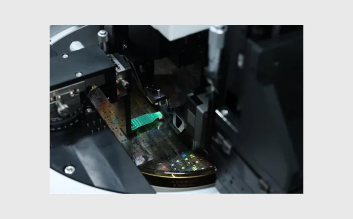
Semight sCT9001 fully automatic Silicon Photonics Wafer Test System is provided with high test accuracy, good test stability and flexible expandability, which is suitable for laboratory verification and mass production testing.
sCT9001 – Semight Instruments SiPh Wafer Test System
- Automatic/Semi-automatic – Support automatic and semi-automatic wafer loading and unloading
- Wafer size – Support 8-inch and 6-inch wafers (4- and 12-inch can be customized)
- Test temperature – Support the test temperature range from room temperature to 150 ℃ (other temperatures can be customized)
- Test function – Support optical-optical test, photoelectric test and electrical parameter test
- DC/AC – Support DC and AC test
- Grating vertical coupling – Grating coupling, FA coupling, and edge coupling
- High efficiency – For different types of chips, support rapid replacement of different types of pin cards
- Software function – The software supports the addition of customer database and MES functions
Functions and advantages
High accuracy probe station:
Wafer loading mode supports fully automatic mode and semi-automatic mode operation, which is suitable for laboratory verification and mass production;
The fully closed-loop high-accuracy motion control system is provided with automatic accuracy compensation function and its positioning accuracy is up to 3um;
The special mechanism design and calibration system can make the wafer on chuck have better planarity and better perpendicularity in Z direction of probe;
A high-definition zooming CCD configured on the system can make the power on PAD clearly visible and display low-magnification and high-magnification multi-view screens at the same time;
The built-in integrated shock-proof design is adopted which can isolate the external vibration and ensure a good test stability;


Coupling test module:
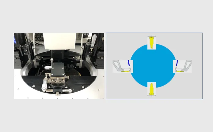
The coupling test module includes coupling optical probe, DC probe and RF probe;
The optical probe supports single-channel coupling and dual-channel coupling;
The optical probe is provided with a high-precision altimeter to ensure the consistency of the height from the incident fiber end face to the chip surface between different chips;
The optical fiber coupling module is composed of a three-dimensional lead screw motor matched with a three-dimensional high-precision piezoelectric ceramic module to ensure the optical coupling efficiency and the optical coupling repeatability;
The standard high-precision coupling controller configured on the system which can help the system realize the functions of fully closed-loop control and hardware synchronization improve the coupling accuracy and coupling speed;
The design of the probe card holder is more convenient for the replacement of the probe card, which is convenient to quickly replace the probe card for different products or different test items;
Test Parameters
| Parameter Type | Test Parameters | Parameter Indicators | Definition |
| O/O | Insert Loss | dB/cm | Insert transmission loss |
| Coupling Strength | % | Coupling efficiency, the ratio of the optical power received by the DUT to the incident optical power | |
| Polarization Dependent Loss | dB | Polarization-dependent loss refers to the ratio of the maximum power to the minimum power after different polarization states pass through the DUT when the polarization state of the transmitted optical signal changes in all polarization states. | |
| Wavelength Scan | dBm | Full wavelength scanning | |
| 3dB bandwidth | Hz | 3dB bandwidth test | |
| O/E | PD Responsivity | A/W | PD responsivity, the efficiency of PD detector converting the received light into current |
| Modulator ER | dB | Static extinction ratio, the ratio of the maximum value to the minimum value of the optical power absorbed by the modulator under different bias voltages | |
| E/E | PD Dark Current | nA | PD dark current, the feedback current measured by increasing the bias voltage to the PD under no-light conditions |
| Heat Resistance | Ω | Thermal impedance |
System Test Indicator
| No. | Specification | Indicator |
| 1 | Support wafer size | 6-inch ~ 8-inch (customization: 4-inch, 12-inch ) |
| 2 | Temperature range | RT~150℃ |
| 3 | Temperature uniformity | <±0.5℃ |
| 4 | 25℃→150℃ | <15 mins |
| 5 | 150℃→25℃ | <30 mins (manual station) |
| 6 | Loading and unloading method | Automatic and manual |
| 7 | Single coupling time | <2s (spiral trajectory length <300μm) |
| 8 | Coupling repetition difference | <0.2dB (individual channel) |
| 9 | Test type | DC test, which can be upgraded to support AC |
| 10 | Test items | O/O,O/E,E/E |
| 11 | Bandwidth test deviation | <1.5G |
| 12 | Wafer Map function | It can be edited, can automatically generate Map and display each Die coordinate |
| 13 | Sub-Bin function | It supports sub-Bin function, can distinguish test results by multiple colors and display the number and proportion of different colors |
| 14 | Automatic needle cleaning function | Support |
| 15 | CCD auto-focus function | Support |
| 16 | Camera monitoring screen | Support low-magnification and high-magnification multi-view screens |
| 17 | EMI shielding | >20dB @1KHz-1MHz |
| 18 | Spectral noise basement | ≦150dBVrms/rtHz(≦1MHz) |
| 19 | System AC noise | ≦15mVp-p(≦1GHz) |
