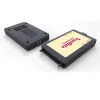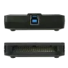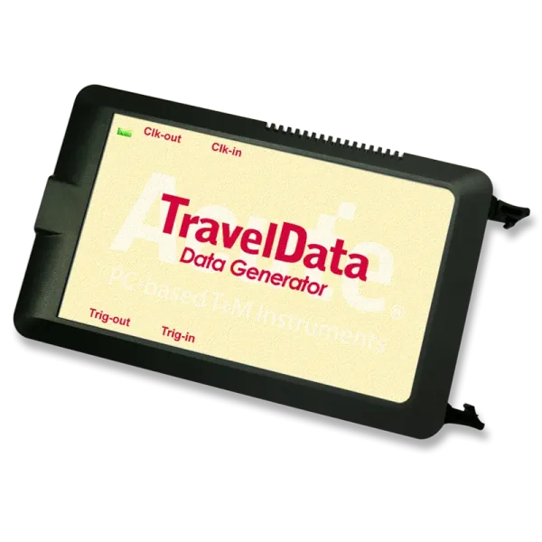
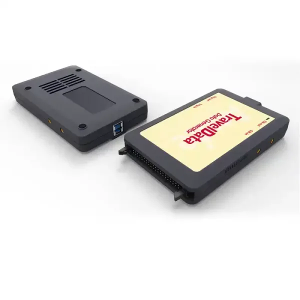
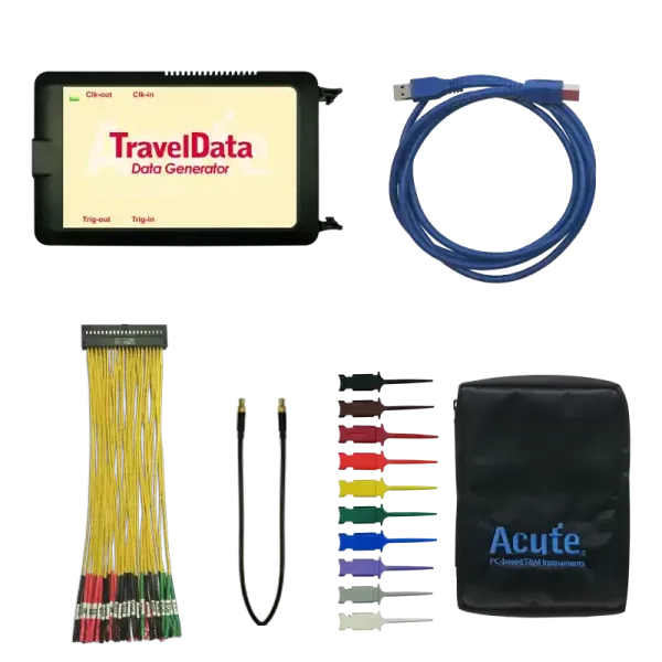
TD3008E Digital Pattern Generator
Digital Pattern Generator
• PC-based
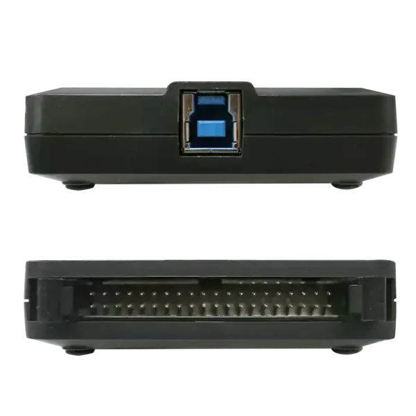
• USB 3.0 Interface
• Channels : 8 (Data Output), 3 (Event Input)
• Data rate : 100Mbps @Ch (Max.)
• Memory: 512Kb/ch
• Clock Range : 1Hz ~ 200MHz (6 digits)
• Data output : 0.9Vpp ~ 4.5Vpp (0.1V resolution) and Hi-Z
• Default pattern : I²C, MIPI I3C, MIPI RFFE, PMBus, PWM, SPI, Sync / Async-Counter, …
• User pattern : Direct draw, Acute-LA / VCD, CSV (MIPI I3C, MIPI RFFE), …
The TD3008E features 8 independent channels, each capable of generating digital signals independently, making it suitable for multi-channel system testing. It is used for signal emulation and reproduction, and it can be controlled using commands to set signal transmission rules. It allows for importing various signal source data files or editing signal formats.
It supports multiple communication protocols, including MIPI I3C, SVI3, SVID, and more. It can be used for testing and verifying various communication interfaces for different applications during the development phase. The digital waveform generator can simulate data and transmit it to ICs for validation testing. This assists in confirming the correctness and performance of ICs, ensuring that ICs operate as expected in real-world applications. It helps in early detection and resolution of potential issues and ensures the successful application of products in the market.
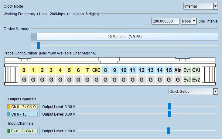
Set CH0~CH15/Ev0-2/CKO/CKI output/input voltage
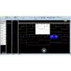
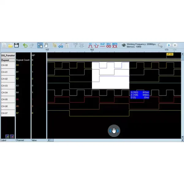
Waveform Editor
- Open New page on Waveform Editor:Switch to the Waveform Editor, you can draw waveform by manual.
- Convert current plugin settings (waveform) to Waveform Editor (Single).
- Convert current plugin settings (waveform) to Waveform Editor (Repetitive).

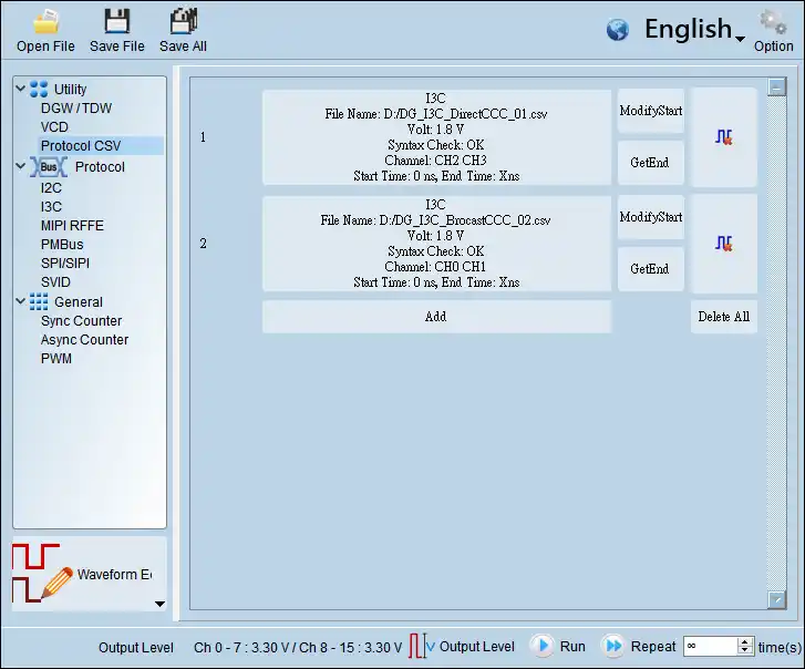
Supports 2 sets of MIPI I3C waveforms.
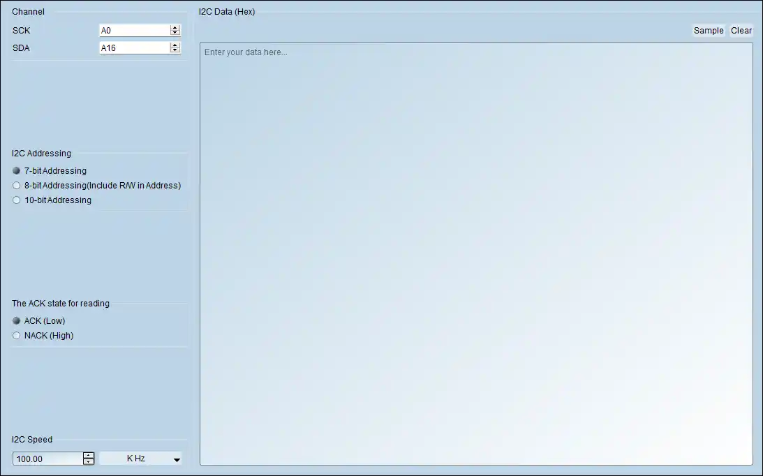
I2C Settings
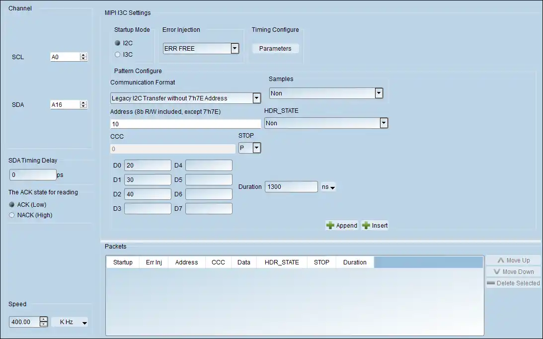
MIPI I3C Settings
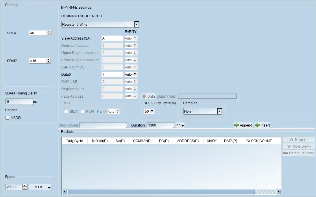
MIPI RFFE Settings
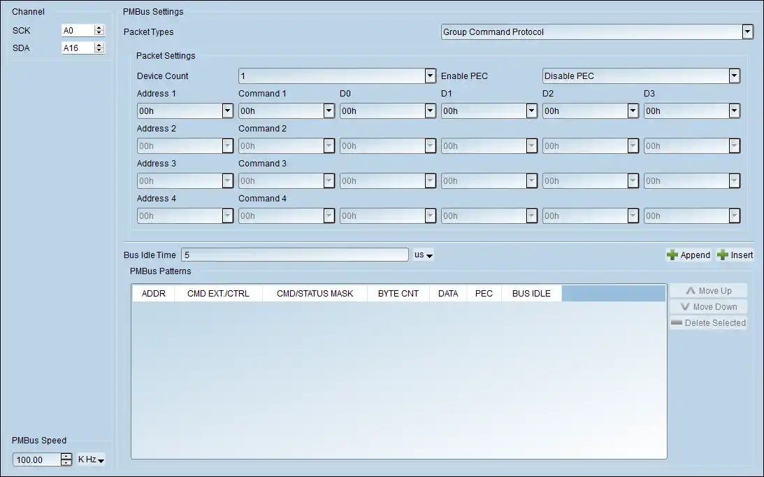
PMBus Settings
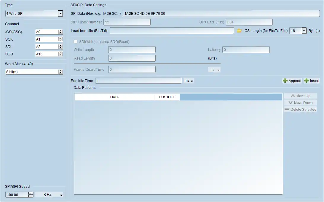
SPI/SIPI Settings
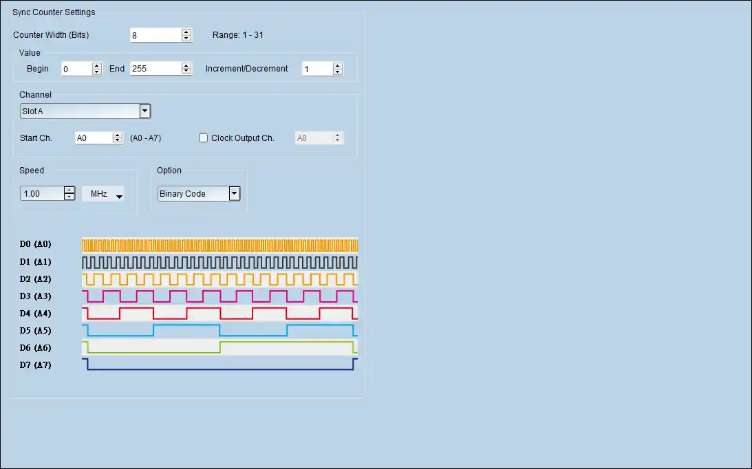
Sync Counter Settings
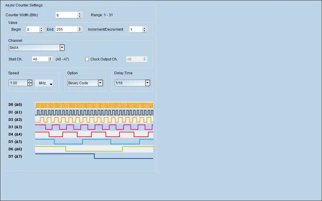
Async Counter Settings
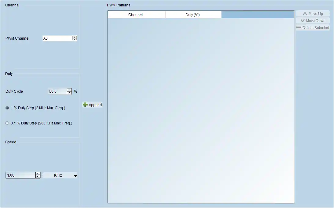
PWM Settings
| Power Source | USB 3.0 |
| Static Power Dissipation | 2.5W |
| Max Power Dissipation | 4.5W |
| Hardware Interface | USB 3.0 |
| Number of Output Chs | 8 |
| Memory Pattern Depth/ch | 512Kb |
| Data Rate | 100Mbps @Ch (Max.) |
| Internal Clock System Range | 1Hz ~ 100MHz |
| Internal Clock System Resolution | 6 digits |
| External Clock System Range | <100MHz |
| Threshold | ±5V |
| Data Flow Control | Loop, Jump, Hold, Wait for Event |
| Clock / Channel Period Jitter | <200ps |
| Internal Event | N/A |
| External Event Ch | N/A |
| External Event Mode | N/A |
| External Event Threshold | N/A |
| Phase Tuning Delayed Time | N/A |

