Liquid Cooled fanSINKS
LQHS – Liquid Cooled Heat Sink
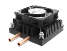
For cooling high heat components, LQHS heat sinks combine an active fan mounted to a heat spreading base with internal channels of flowing coolant.With the liquid assist, LQHS heat sinks provide thermal performance at least three times higher than fan-assisted heats sinks without liquid loops.
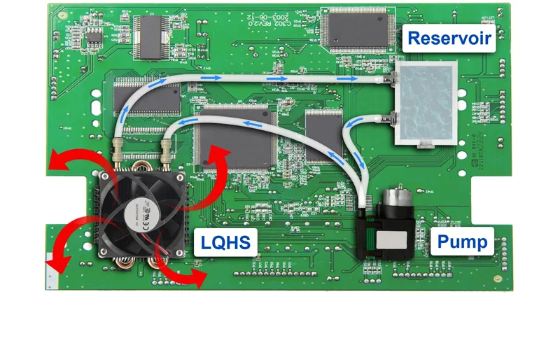
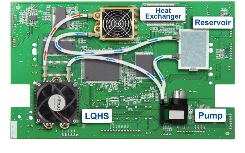
LQHS heat sinks are combined with pumps and coolant reservoirs to provide continuous, high-level cooling of hot CPUs, GPUs, FPGAs, and AI processors, along with IFBT, MOSFETs and DC-DC converters. For even higher cooling levels, a heat exchanger can be added to the liquid-cooling configuration. ATS provides recommendations for (non-included) fans per user application.
- Internal Diameter: 4.826 mm Outside Diameter 6.35 mm Tube Length: 488.5 mm
- Pin fin heat sinks are anodized black
- Sizes of 84.00×84.00 mm and 84.00 mm
- Heights of 25.80 mm and 30.80 mm
- Tubes are copper
- Stainless steel screw fan attachment ensures dependable long-term fan to heat sink assembly. 4-40 thread screws are supplied in 4 lengths (1/2”, 3/4”,7/8”, 1”).
- Fan assembly hole pattern is 50.0 mm C-C (center to center)
- Includes Thermal Interface Material (TIM) centered on base.
- Recommended through hole size in PCB is 3.00 mm
- Thermal performance is at least 3x better than the exact same size fanSINK without the liquid loop.
- Integrated HEX, hence, the liquid loop may require one less component.
- LQHS’ thermal performance is equal or better than the same size cold plate with the same fluid flow rate
- Its performance is equal or better than to the same heat sink with vapor chamber
- Fluid Types: Water, Propylene Glycol, Refrigerants, Dielectrics, Mineral Oil, EG Mixtures
- Fan not included please see table of suggested fans for each part number
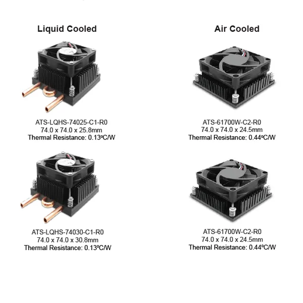
Thermal Resistance Comparison of Similar Heat Sinks: Liquid Cooled vs. Air Cooled

- CPU, GPU, FPGA or AI Processor cooling
- Cooling of Mosfets, DC-DC converters
- IGBT cooling
- Small industrial laser cooling
- Cooling of AI-Personal Computers
- Edge Compute Server Cooling
Application Examples
Example Liquid Loop Configurations and Components

This configuration relies on the LQHS’ integrated heat exchanger. This reduces the cost and complexity of this liquid cooling solution and features a thermal resistance of 0.05°C/W.

For very high heat applications, a heat exchanger can be included in the liquid loop. This will with This configuration relies on the LQHS’ integrated heat exchanger. This reduces the cost and complexity of this liquid cooling,
* If you need Datasheet, RoHS or CAD, please contact us.
| Part Number | Lifecycle Status |
Dimension (mm) | Flow Rate LPM(GPM) 1.9(0.5) |
Flow Rate LPM(GPM) 3.7(1.0) |
Flow Rate LPM(GPM) 5.7(1.5) |
Flow Rate LPM(GPM) 7.6(2.0) |
||||||
|---|---|---|---|---|---|---|---|---|---|---|---|---|
| L | W | H | R (°C/W) |
dP kPA (psi) |
R (°C/W) |
dP kPA (psi) |
R (°C/W) |
dP kPA (psi) |
R (°C/W) |
dP kPA (psi) |
||
| ATS-LQHS-74025-C1-R0 | ACTIVE | 74 | 74 | 25.8 | 0.13 | 3 (0.44) |
0.122 | 13 (1.89) |
0.116 | 27 (3.92) |
0.114 | 47 (6.82) |
| ATS-LQHS-74030-C1-R0 | ACTIVE | 74 | 74 | 30.8 | 0.13 | 3 (0.44) |
0.122 | 13 (1.89) |
0.116 | 27 (3.92) |
0.114 | 47 (6.82) |
| ATS-LQHS-84025-C1-R0 | ACTIVE | 84 | 84 | 25.8 | 0.06 | 10 (1.45) |
0.05 | 36 (5.22) |
0.05 | 77 (11.17) |
0.05 | 134 (19.43) |
| ATS-LQHS-84030-C1-R0 | ACTIVE | 84 | 84 | 30.8 | 0.06 | 10 (1.45) |
0.05 | 36 (5.22) |
0.05 | 77 (11.17) |
0.05 | 134 (19.43) |

