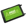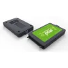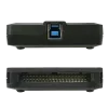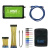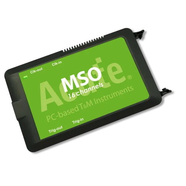
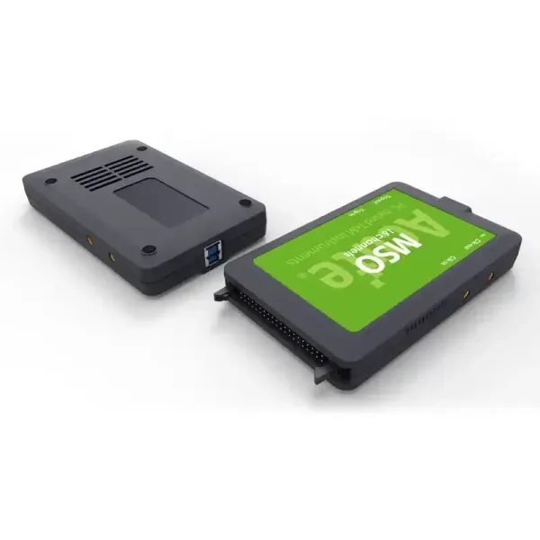
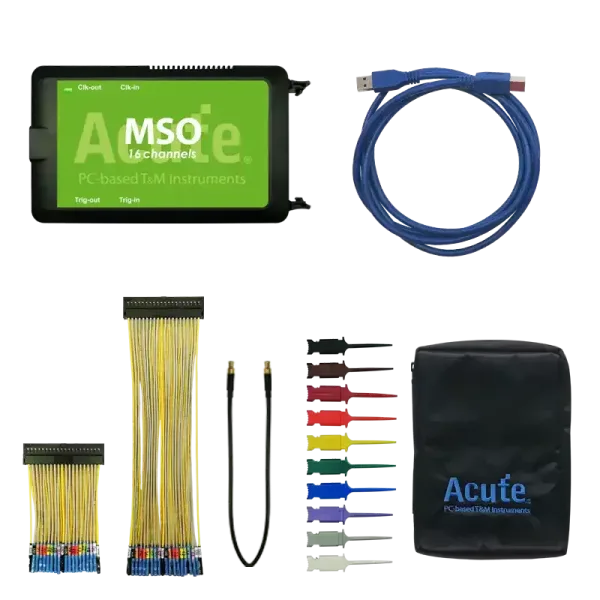
MSO2216B Mixed Signal Oscilloscope
MSO2000 Mixed Signal Oscillosc
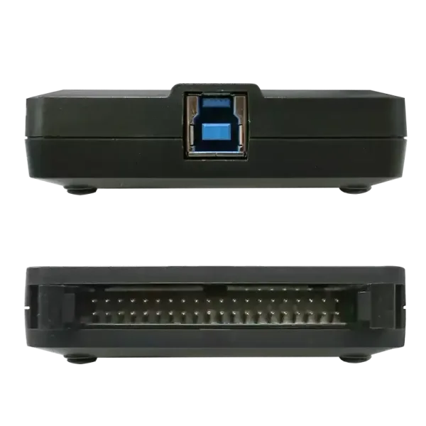
- PC-based, USB3.0 interface
- 16 Channels (display digital and analog waveforms of the same channel)
- Digital Inputs : 2 GHz Timing, 200MHz State Analysis
- Analog Inputs : 200 MS/s (Max.), Bandwidth 40 MHz
- 8 Gb Memory
- PC RAM storage for streaming mode
- Utility model patent of Taiwan number M601827
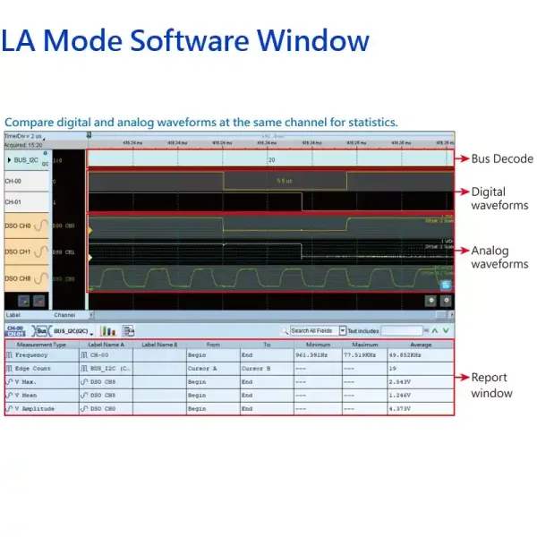
The MSO2000 series is a 16-channel 3-in-1 (logic, protocol, and oscilloscope) analyzer, with each channel supporting simultaneous measurement of both analog and digital signals. When measuring power management-related protocols, it can not only decode the protocols but also simultaneously record voltage values. Currently, the MSO2000 series offers two different signal and bus analysis modes: logic analyzer mode and protocol analyzer mode.
In the past, many users had questions or were unclear about the voltage threshold settings in the logic analyzer. Therefore, Acute has added a one-click automatic voltage threshold detection and configuration feature in the MSO2000 series products to save users the time required for configuration.
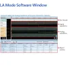
Logic Analyzer (LA) Mode
- Capture digital waveforms and support bus decodes. Able to stack with a DSO to form as an MSO.
- Provides multiple storage modes, users could select to have long time recording or precision acquisition.

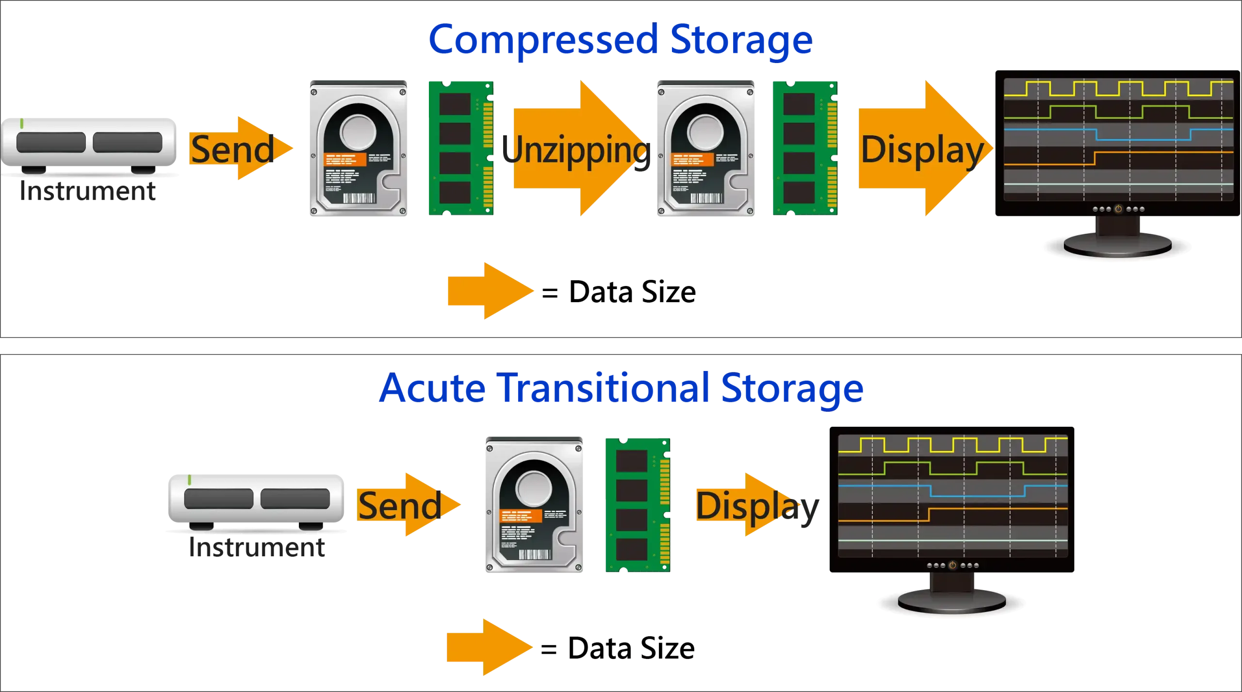
Long Time Record: Transitional Storage VS Compressed Storage
For signal capture and analysis, usually require to record the signal for a long time. If the data is stored in a compressed way, it will cause your software to lag or even stop functioning when decompressing the data after it is sent back to the computer. Because PC memory size might insufficient for decompressed data size. To satisfy the requirement of smooth software operation and long-term recording without missing any data, the storage method adopted by the Acute analyzer is transitional storage rather than compression. After returning to the PC software, it doesn”t need to do the decompression. The decoded results can be displayed while the analysis is finished.
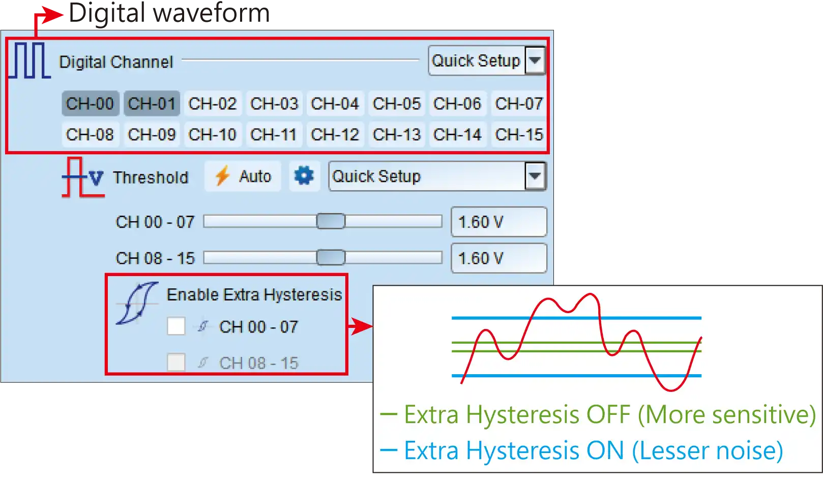
Digital and Analog Waveform Settings
Each channel supports both digital and/or analog waveforms measurements, voltage resolution can be changed between 2 levels for all channels at the same time
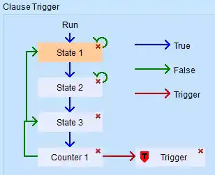
Flow chart bus triggers
Power trigger for serial bus, 8-states flow chart setting with Counter/Timer
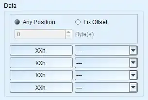
Detail parameters for each states
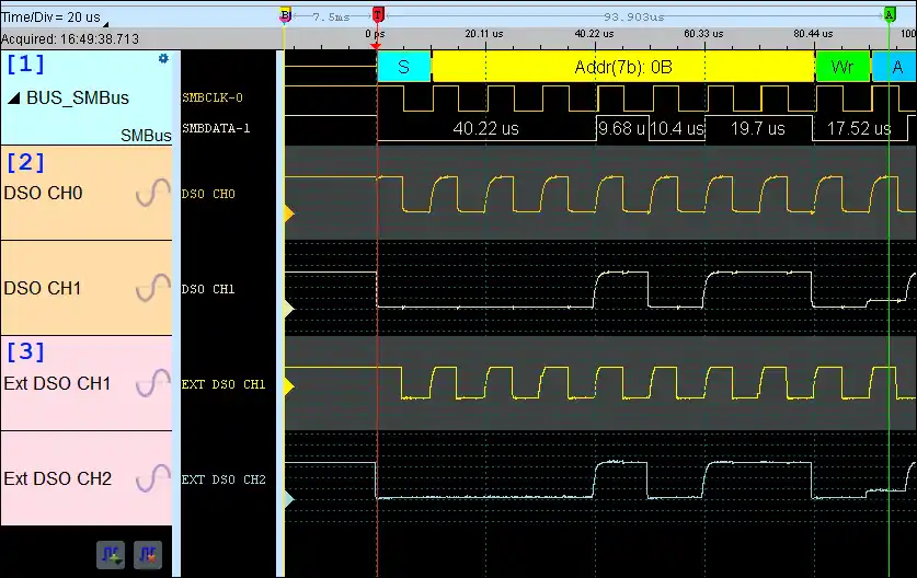
Stack With Other Vendors of Oscilloscope
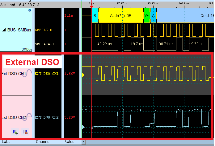
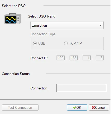
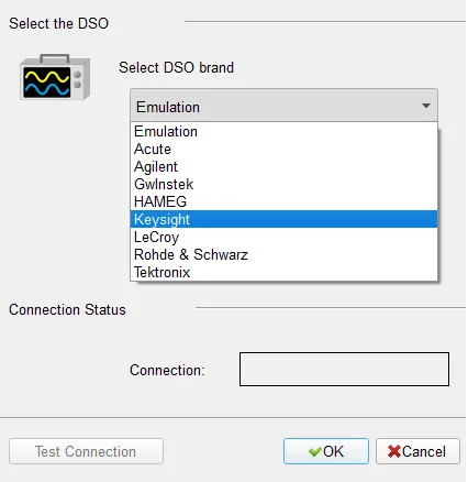
MSO Enables Digital & Analog Channels
(Using the same channels)a
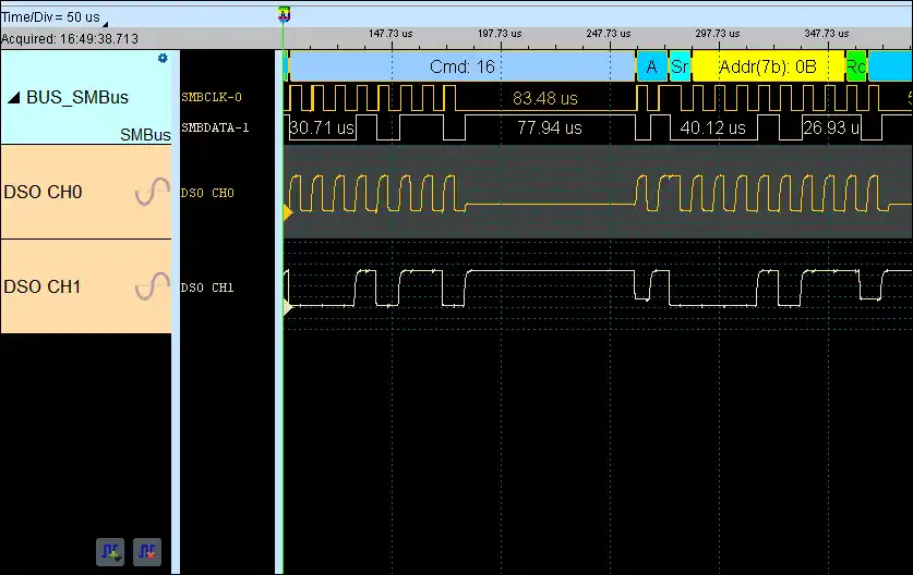
Digital & Analog Signals From MSO and External DSO From Other Vendors
*[1]: Decode & Digital Signals;*[2]: MSO Analog Signals;*[3]: External DSO Signals
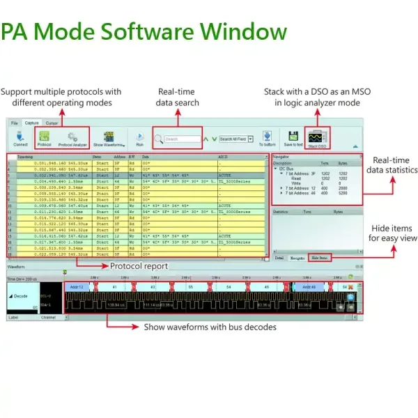
Protocol Analyzer (PA) Mode
It is hardware decoding, may log protocol data very long time if without waveforms. Application timing: Preliminary protocol debug.
Protocol Analyzer
Show real-time protocol data. Application timing: massive protocol data with some idles in between.
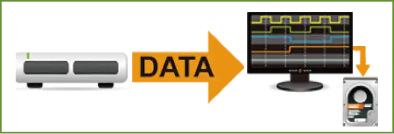
Protocol Logger
Like data logger, save massive data into SSD hard drive. Application timing: massive protocol data.

Protocol Monitor
Like dash cameras, record protocol data by the device’s memory only. Application timing: trigger event only happens in very long time.

| DSO Spec. | |
|---|---|
| Power source | USB bus-power (+5V) |
| Static power consumption | 0.9W |
| Max power consumption | <6W |
| Acquisition Mode | N/A |
| 8 bits Sampling [Record length] | N/A |
| ≧12 bits Sampling [Record length] | 200MHz |
| ≧14 bits Sampling [Record length] | N/A |
| Input channels | 16 |
| Input coupling | N/A |
| Input impedance | N/A |
| Overvoltage protection | N/A |
| Ch-Ch isolation | N/A |
| Ch-Ch skew | N/A |
| Bandwidth | 40 MHz |
| Rise time | N/A |
| Resolution | 12 bits |
| Input sensitivity | N/A |
| Offset range | N/A |
| DC accuracy | N/A |
| Bandwidth limit | N/A |
| Protocol Trigger / Decode | N/A |
| Electrical Validation (Protocol) | N/A |
| Cascade | N/A |
| LA Spec. | |
| Power source | USB bus-power (+5V) |
| Static power consumption | 0.9W |
| Max power consumption | <6W |
| Hardware Interface | USB 3.0 |
| Timing Analysis (Asynchronous,Max. Sample Rate) | 2 GHz |
| State Clock Rate (Synchronous,External Clock) | 200 MHz |
| Storage | Conventional Timing, Transitional Timing |
| Channels | 16 |
| Total Memory | 8Gb |
| Timing Analysis | Available Chs (Conventional / Transitional Timing) – Memory per Ch |
| 4GHz Timing [Available Chs] – Memory per Ch | N/A |
| 2GHz Timing [Available Chs] – Memory per Ch | [8/7] – 1Gb |
| 1GHz Timing [Available Chs] – Memory per Ch | [16/14] – 512Mb |
| 500MHz Timing [Available Chs] – Memory per Ch | [16/16] – 512Mb |
| 250MHz Timing [Available Chs] – Memory per Ch | [16/16] – 512Mb |
| Channel to channel skew | < 1ns |
| Input channels | N/A |
| Input impedance | 1MΩ//2pF |
| Max. (Non-destructive) | over ±42V DC & AC |
| Input operation | ±20V / ±10V (Standard / High Resolution) |
| Input sensitivity | 200MHz (1Vpp) |
| Threshold group | 2 (CH0~7 & CKI, CH8~15) |
| Threshold range | ±20V |
| Threshold resolution | 50mV |
| Threshold accuracy | ±100mV + 5%*Vth |
| Trigger resolution | 500ps |
| Trigger types | Channel, Pattern, Single / Multi Level, Width, Time-out, Setup/Hold Timing Violation, External, Manual |
| Protocol Trigger | BiSS-C, CAN2.0B/CAN FD, DALI, DP_Aux, eMMC 4.5, eSPI, HID over I2C, I2C, I2S, LIN2.2, LPC, MDIO, MII, Mini/Micro LED, MIPI I3C 1.1.1, MIPI RFFE 3, MIPI SPMI 2, Modbus, PMBus, Profibus, RGMII, RMII, SD 2.0 (SDIO 2.0), SENT, Serial Flash (SPI NAND), SMBus, SPI, SVI2, SVI3, SVID, UART (RS232), USB PD 3, USB1.1 |
| Protocol Analyzer | BiSS-C, CAN2.0B/CAN FD, DALI, DP_Aux, eSPI, HID over I2C, I2C, I2S, LIN2.2, MDIO, MII, MIPI I3C 1.1.1, MIPI RFFE 3, Modbus, PMBus, Profibus, PWM, RGMII, RMII, SMBus, SPI, SVI3, SVID, UART (RS232), USB PD 3, USB1.1 |

