S2028H
S2028H – Semight Instruments Dual-Channel Precision Source Meter
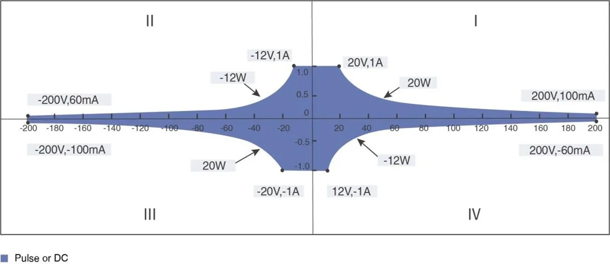
The Semight S2028H is a compact and cost-effective single channel desktop power supply/measurement unit (SMU), which has a wide range of voltage source (± 60V) and current source (± 3A DC and ± 10A pulse) functions, excellent accuracy, 6-and-a-half-bit display (minimum 100fA/100nV display resolution), and excellent color LCD graphical user interface (GUI).
S2028H – Semight Instruments Dual-Channel Precision Source Meter
- High range – ±60 V、±3 A (DC)、±10A (Pulse)
- High resolution – The minimum measurement resolution can reach 100 fA/100 nV
- High sampling rate -Supports up to 1M ADC sampling rate
- Threshold trigger – Hardware high-speed IO, capable of threshold triggering, enabling efficient interaction between output measurement values and user systems
Features and Benefits
DC I-V output capability


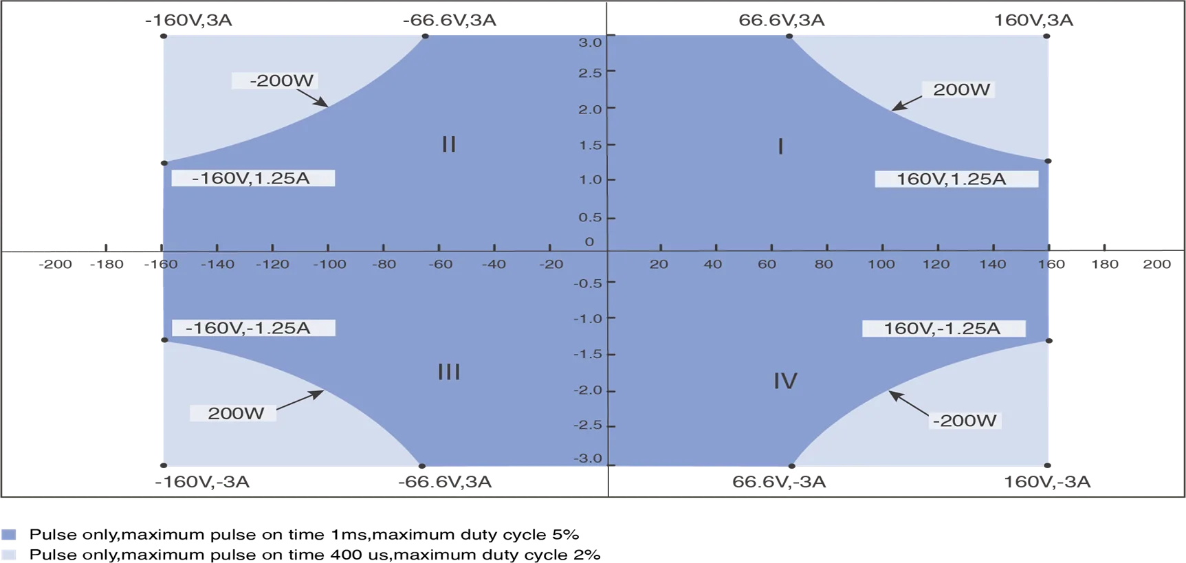
Pulse I-V output capability
Voltage source/ measurement specifications
| Voltage accuracy | Range | Programming resolution | Accuracy (1 Year)
± (% reading+ offset) |
Typical Noise (RMS)
0.1 Hz-10Hz |
| ±60 V | 10 μV | 0.02%+3 mV | 200 μV | |
| ±6 V | 1 μV | 0.02%+0.3 mV | 60 μV | |
| ±0.6 V | 100 nV | 0.02%+50 μV | 20 μV | |
| Temperature coefficient | ±(0.15 × accuracy)/℃ (0℃-18℃,28℃-50℃) | |||
| Settling time | <50 μs (typical) | |||
| Overshoot | <±0.1% (Typical. Normal mode. Step is 10 % to 90 % range, full range, resistive load) | |||
| Noise 10 Hz-20 MHz | 6V voltage source, 3A resistive load, <5 mVrms | |||
Current source/ measurement specifications
| Current accuracy | Range | Programming resolution | Accuracy (1 Year)
± (% reading+ offset) |
Typical Noise (RMS)
0.1 Hz-10 Hz |
| ±10 A1 | 1 μA | 0.03% + 2mA | 20 μA | |
| ±3 A | ||||
| ±1 A | 100 nA | 0.03% + 90 μA | 3 μA | |
| ±100 mA | 10 nA | 0.03% + 9 μA | 200 nA | |
| ±10 mA | 1 nA | 0.03% + 900 nA | 20 nA | |
| ±1 mA | 100 pA | 0.03% + 90 nA | 2 nA | |
| ±100 μA | 10 pA | 0.03% + 9 nA | 200 pA | |
| ±10 μA | 1 pA | 0.03% +1 nA | 30 pA | |
| ±1 μA2 | 100 fA | 0.03% + 200 pA | 5 pA | |
| Temperature coefficient | ±(0.15 × accuracy)/℃ (0℃-18℃,28℃-50℃) | |||
| Settling time | <100 μs (typical) | |||
| Overshoot | <±0.1% (Typical. Normal mode. Step is 10 % to 90 % range, full range, resistive load) | |||
- 10A range is available only for pulse mode, accuracy specifications for 10A range are typical.
- Low Current Measurements, Triaxial Cable is recommended to connect: HI connect to core cable, Guard connects to inner shield, outer shield connects to protective ground, LO connect to core cable, inner shield not connect, and outer shield connect to protective ground. Triaxial Cable rated insulation voltage is not less than 250V.
Pulse source specifications (4W)
| Minimum programmable pulse width | 100 μs |
| Pulse width programming resolution | 1 μs |
| Pulse width programming accuracy | ±10 μs |
| Pulse width jitter | 2 μs |
| Pulse width definition | The time from 10 % leading to 90 % trailing edge as follows |

| Item | Maximums | Maximum pulse width | Maximum duty cycle |
| 1 | 0.4 A/50 V | DC, no limit | 100% |
| 2 | 1 A/20 V | DC, no limit | 100% |
| 3 | 3 A/6.6 V | DC, no limit | 100% |
| 4 | 10 A/20 V | 1 ms | 5% |
| 5 | 10 A/50 V | 400 μs | 2% |
Typical Pulse Performance(4W)
| Source | Maximum output | Typical rise time 1 | Typical Settling Time2 | Test load |
| Voltage | 50 V | 250 μs | 400 μs | NO load |
| 5 V | 40 μs | 100 μs | NO load | |
| Current | 10 A~100 μA | 90 μs | 250 μs | Full load3 |
| 10 μA | 120 μs | 300 μs | Full load3 | |
| 1 μA | 300 μs | 600 μs | Full load3 |
- Leading edge, the time from 10 % leading to 90 % leading
- The time required from Pulse out 0 to reach within 1 % of final value
- Test condition: Normal, resistive load 6V maximum output
Typical output settling time
| Source | Range | Output settling time1 | Condition | ||
| Fast2 | Normal | Slow | |||
| Voltage | 60 V | <120 μs | <300 μs | <1 ms | Time required to reach within 0.1 % of final value at open load condition. Step is 10 % to 90 % range |
| 6 V | <30 μs | <50 μs | <300 μs | ||
| 0.6 V | <30 μs | <50 μs | <300 μs | ||
| Current | 3 A~100 μA | <50 μs | <100 μs | <0.8 ms | Time required to reach within 0.1 % (0.3 % for 3 A range) of final value at short condition. Step is 10 % to 90 % range |
| 10 μA | <100 μs | <150 μs | <0.8 ms | ||
| 1 μA | <300 μs | <400 μs | <1 ms | ||
- Output transition speed:Fast, Normal, Slow. Users can adjust the APFC parameters based on the load characteristics to obtain precision, and fast output characteristics
- Slow mode is recommended for overshoot sensitive equipment, Fast mode may have overshoot on output in some condition
