
10-Pin Split Cable
TP240212
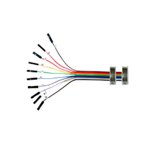
The 10-Pin Split Cable attaches to the ribbon cables on the Aardvark™ I2C/SPI Host Adapter, the Cheetah™ SPI Host Adapter, the Beagle™ I2C/SPI Protocol Analyzer, and the Promira Serial Platform. The 10-Pin Split Cable is an ideal solution if you don’t have space for a 5×2 0.100″ header on your test board and need individual leads for each pin. It also allows use of a header that doesn’t have the same pin-out as your Total Phase host adapter/protocol analyzer.
- Includes a 10-pin box header that attaches to the ribbon cable
-
Connector is a standard 5×2 0.100″ (2.54mm) pitch IDC type keyed box connector
-
Cable will connect to any standard 0.100″ (2.54mm) pitch 10-pin keyed IDC-type connector
-
Cable is 5 inches (12.7cm) long to minimize signal degradation
-
Each individual lead is terminated with a single pin crimp connector with the same 0.100″ (2.54mm) pitch
-
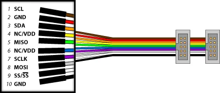
Each individual lead has a different color and is labeled with the pin name for easy identification
Download Aardvark I2C/SPI Host Adapter Data Sheet
Download Aardvark OEM I2C Host Adapter Data Sheet
Download Aardvark OEM SPI Host Adapter Data Sheet
Download Advanced Cable Tester v2 Data Sheet
Download Beagle I2C/SPI Protocol Analyzer Data Sheet
Download Beagle USB 12 Protocol Analyzer Data Sheet
Download Beagle USB 480 Protocol Analyzer Data Sheet
Download Beagle USB 480 Power Protocol Analyzer Data Sheet
Download Beagle USB 5000 v2 SuperSpeed Ultimate Protocol Analyzer Data Sheet
Download Cheetah SPI Host Adapter Data Sheet
Download Advanced Cable Tester v2 User Manual
Download A2B Bus Monitor User Manual
Download USB Power Delivery Analyzer User Manual
Download Promira Serial Platform I2C/SPI Active User Manual
Download Promira Serial Platform eSPI Analyzer User Manual
Download Promira Serial Platform System User Manual
Download Komodo CAN Interface User Manual
Download Cheetah SPI Host Adapter User Manual
Download Beagle Protocol Analyzer User Manual
Tech Specs
| I2C/SPI | eSPI | # | # | I2C/SPI | eSPI | |
|---|---|---|---|---|---|---|
| SCL/GPIO00 | Alert0 | 1 | 2 | GND | GND | |
| SDA/GPIO01 | Alert1 | 3 | 4 | VTGT | VTGT | |
| MISO/IO1 | IO1 | 5 | 6 | VTGT | VTGT | |
| SCLK | SCK | 7 | 8 | MOSI/IO0 | IO0 | |
| SS0/GPIO02 | CS0 | 9 | 10 | GND | GND |
- I2C Master: 1 kHz – 800 kHz
- SPI Master: 125 kHz – 8 MHz
- SPI Slave: 0.1 MHz – 4 MHz


