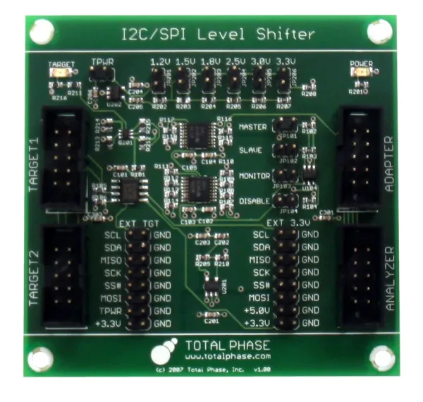
Level Shifter Board
TP240610
The Level Shifter Board provides embedded systems engineers with an easy and cost-effective method for interfacing Total Phase’s products with lower logic level devices. The Level Shifter Board is capable of down-shifting to all standard logic levels from 1.2 V to 3.3 V for the Aardvark™ I2C/SPI Host Adapter, the Beagle™ I2C/SPI Protocol Analyzer, and the Cheetah™ SPI Host Adapter. Engineers can also choose to power downstream devices.
- Level shifting for I2C, SPI, MDIO, and GPIO signals
- Supports voltage levels of 1.2V, 1.5V, 1.8V, 2.5V, 3.0V, and 3.3V
-
Supply power to downstream devices
-
I2C speeds of 800 kHz
-
SPI and MDIO speeds of 20 MHz
Beginners Guide to the I2C/SPI Level Shifter Board
I2C/SPI Product Guide
 |
 |
 |
||
|---|---|---|---|---|
| Part Number | TP240141 | TP280121 | TP500110 | TP320121 |
| User Manual | HTML | HTML | HTML | HTML |
| Datasheet | ||||
| RoHS Compliant | ||||
| I2C Master | Up to 800 kHz 1 |
Up to 3.4 MHz |
||
| I2C Slave | Up to 800 kHz 1 |
Up to 3.4 MHz |
||
| SPI Master | Up to 8 MHz 2 |
up to 40 MHz+ 3 |
Up to 80 MHz |
|
| SPI Slave | Up to 4 MHz 2 |
Up to 20 MHz |
||
| GPIO | Up to 16 |
|||
| I2C Monitor | up to 4 MHz |
|||
| SPI Monitor | up to 24 MHz |
|||
| Windows, Linux & Mac OS X | ||||
| USB Bus Powered Device | Full-Speed |
High-Speed |
High-Speed |
High-Speed |
| Software GUI | ||||
| Development API / DLL | ||||
| LabVIEW Driver | ||||
| Dimensions | L: 3.5″ (8.9 cm) W: 1.6″ (4.1 cm) D: 0.9″ (2.2 cm) |
L: 3.5″ (8.9 cm) W: 1.6″ (4.1 cm) D: 0.9″ (2.2 cm) |
L: 4.55″ 11.6 cm) W: 3.05″ (7.7 cm) D: 1.15″ (2.9 cm) |
L: 4.6″ (11.7 cm) W: 2.75″ (7.0 cm) D: 1.1″ (2.8 cm) |
1Actual system bus speed may vary as a function of capacitance.
2The quoted values are intra-byte speeds. Please refer to the datasheet for timing restrictions.
3Customers have successfully over-clocked the Cheetah SPI adapter to 50MHz.
Total Phase also has a number of accessories that can be used in conjunction with the products above.
Download Aardvark I2C/SPI Host Adapter Data Sheet
Download Aardvark OEM I2C Host Adapter Data Sheet
Download Aardvark OEM SPI Host Adapter Data Sheet
Download Advanced Cable Tester v2 Data Sheet
Download Beagle I2C/SPI Protocol Analyzer Data Sheet
Download Beagle USB 12 Protocol Analyzer Data Sheet
Download Beagle USB 480 Protocol Analyzer Data Sheet
Download Beagle USB 480 Power Protocol Analyzer Data Sheet
Download Beagle USB 5000 v2 SuperSpeed Ultimate Protocol Analyzer Data Sheet
Download Cheetah SPI Host Adapter Data Sheet
Download Advanced Cable Tester v2 User Manual
Download A2B Bus Monitor User Manual
Download USB Power Delivery Analyzer User Manual
Download Promira Serial Platform I2C/SPI Active User Manual
Download Promira Serial Platform eSPI Analyzer User Manual
Download Promira Serial Platform System User Manual
Download Komodo CAN Interface User Manual
Download Cheetah SPI Host Adapter User Manual
Download Beagle Protocol Analyzer User Manual
Tech Specs
Power Consumption
- Will draw approximately 6 mA from the Adapter/Analyzer side when configured to power the target device
- Will draw approximately 4 mA when the target is supplying its own power
- Will draw approximately 1 mA on the Target side of the target device is supplying power to the board
Speed
- I2C communication up to 800 kHz
- SPI/MDIO communication up to 18 MHz when shifting to 1.2 V and up to 20 MHz when shifting to 3.3 V*
*This is dependent on specific configurations and the timing specification of the target device
Hardware
- Level Shifter Board
- 1 6″ 10-pin ribbon cable
- 1 1.5″ 10-pin ribbon cable
- 3 jumpers for configuration
Dimensions and Weight
- 3″ x 2.9″ (76.2 mm x 73.7 mm)
- Mounting holes are 0.187 inches diameter

